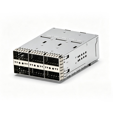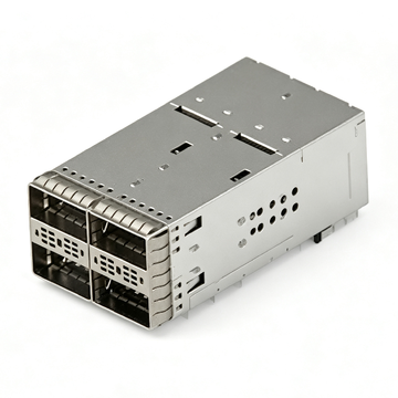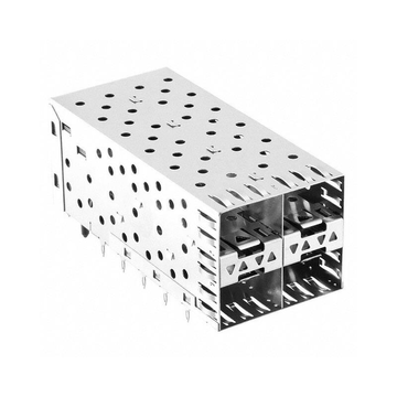
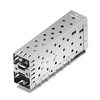
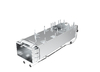
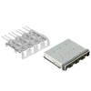

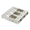

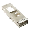
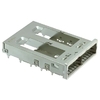
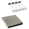
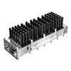


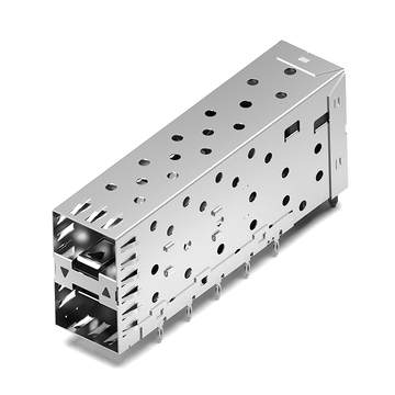



SFP cage assemblies are essential mechanical components in network switches, routers, and other communication equipment. They provide a mounting structure for SFP transceivers, help maintain port alignment, and support electromagnetic interference (EMI) shielding. When an original component becomes difficult to source or its lead time affects production, finding a compatible alternative can help maintain hardware supply continuity.
TE Connectivity 1658391-2 is a 2x1 stacked SFP cage assembly with an integrated connector, through-hole press-fit termination, and internal and external EMI springs. For designs using this configuration, LINK-PP offers the LP21AC02001 as a compatible alternative. It shares the key structural characteristics of the original part, including a 2x1 stacked SFP layout, right-angle mounting, press-fit termination, and EMI springs.
This guide covers the information needed to evaluate the 1658391-2 and its LINK-PP alternative, including:
-
The product structure, main specifications, and typical applications of TE Connectivity 1658391-2.
-
The features and technical specifications of LINK-PP LP21AC02001.
-
A side-by-side comparison of their configurations and important differences.
-
Practical checks for PCB layout, mechanical fit, EMI performance, and operating temperature.
-
Supply options and how to request product information from LINK-PP.
Understanding these details helps engineers and procurement teams assess whether LP21AC02001 is suitable for their existing SFP hardware design and production requirements.
What Is TE Connectivity 1658391-2?
TE Connectivity 1658391-2 is a 2x1 stacked SFP cage assembly with an integrated connector, designed for through-hole press-fit mounting on a PCB. It provides two vertically arranged SFP ports in a compact mechanical configuration and incorporates EMI springs to support shielding around the transceiver interfaces.
Overview of TE Connectivity 1658391-2
The 1658391-2 is designed for equipment that requires two SFP ports arranged vertically in a stacked configuration. Its cage-and-connector assembly combines the metal enclosure with the corresponding electrical interface, providing a structured connection point for pluggable SFP transceivers.
Its main characteristics include:
-
Product type: SFP cage assembly with integrated connector
-
Port configuration: 2x1 stacked
-
Number of ports: 2
-
Number of positions: 40
-
PCB termination: Through-hole press-fit
-
Mounting style: Right-angle board mounting
-
EMI protection: Internal and external EMI springs
-
Lightpipe: Not included
-
Maximum data rate listed by TE: 4Gb/s
-
Maximum contact current: 0.5A
The 2x1 configuration allows two SFP interfaces to occupy a vertically stacked front-panel arrangement. This is useful in network equipment where port density and PCB space are important design considerations.
Structural Features of 1658391-2
The 1658391-2 combines a stacked metal cage with an integrated connector assembly. Its mechanical structure guides SFP modules into the corresponding electrical interfaces while helping maintain alignment and shielding around the ports.
Important structural features include:
-
Stacked SFP cage: Two ports are arranged vertically in a 2x1 configuration.
-
Press-fit PCB termination: The assembly uses through-hole press-fit contacts rather than a conventional surface-mount termination.
-
Right-angle mounting: The port openings face the equipment's front panel while the assembly connects to the PCB.
-
EMI springs: Internal and external springs help establish electrical contact between the cage and surrounding shielding structures.
-
No integrated lightpipe: The assembly does not include a lightpipe for front-panel LED indication.
These features make the component suitable for hardware designs that use stacked SFP interfaces and require a press-fit cage assembly. The actual PCB footprint and mechanical envelope should always be checked against the manufacturer's drawing before layout approval or replacement.
Typical Applications of 1658391-2
The 1658391-2 is intended for SFP-based pluggable I/O applications, particularly equipment that uses stacked port arrangements. Its form factor can support compact network hardware where multiple interfaces must be placed within limited front-panel space.
Typical application areas include:
-
Ethernet switches and network routers
-
Enterprise networking equipment
-
Data communication hardware
-
Telecommunications equipment
-
Network interface and embedded communication systems
The cage itself is a mechanical and shielding component. The supported data rate of the complete interface depends on the connector design, PCB routing, transceiver, and overall system implementation.
1658391-2 Datasheet and Technical Specifications
The TE Connectivity 1658391-2 datasheet identifies the part as a stacked SFP cage assembly with an integrated connector, 40 positions, two ports, and through-hole press-fit termination. Its published maximum data rate is 4Gb/s, and its operating temperature range is -55°C to +105°C.
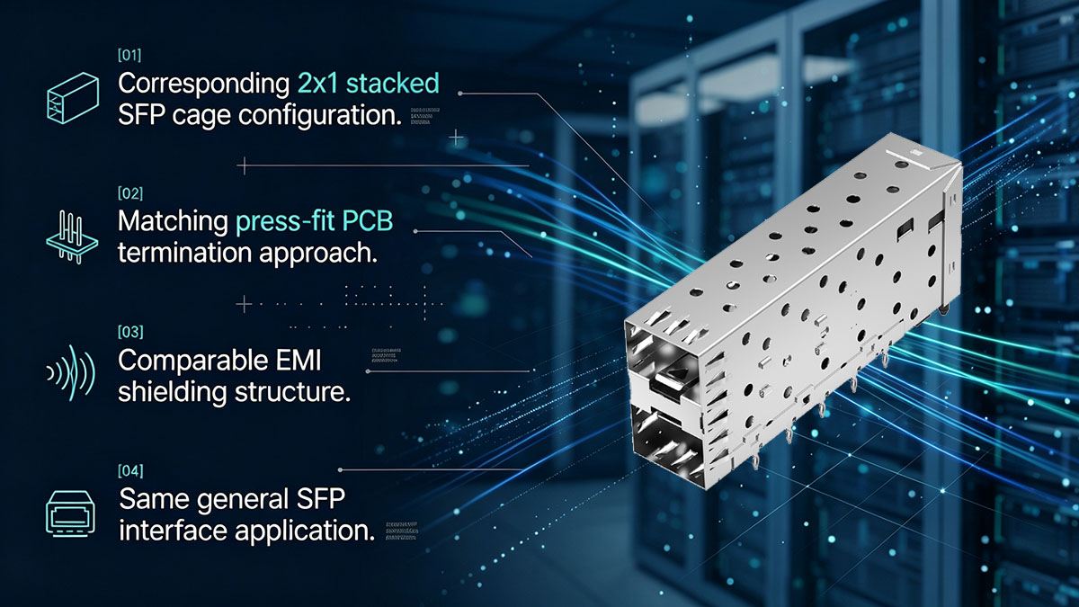
Electrical and Interface Specifications
The electrical specifications describe the connector's interface configuration and the ratings published for the assembly. These values should be considered alongside the system-level signal-integrity requirements.
| Parameter | TE Connectivity 1658391-2 |
|---|---|
| Connector type | SFP |
| Product type | Cage assembly with integrated connector |
| Port configuration | 2x1 stacked |
| Number of ports | 2 |
| Number of positions | 40 |
| Maximum data rate | 4Gb/s |
| Maximum contact current | 0.5A |
| Circuit application | Signal |
| PCB termination | Through-hole press-fit |
| Contact pitch | 0.8mm |
The 4Gb/s maximum data rate is the value listed for this TE part. It should not be interpreted as a guarantee of system-level performance in every host design. PCB routing, connector implementation, signal integrity, and the selected transceiver all affect the performance of the complete interface.
Mechanical and Mounting Specifications
The mechanical configuration determines how the cage aligns with the PCB, front panel, and SFP transceivers. For the 1658391-2, the 2x1 stacked arrangement and through-hole press-fit mounting are central design characteristics.
Key mechanical details include:
-
Stacked 2x1 port arrangement
-
Two SFP port openings
-
Right-angle board mounting
-
Through-hole press-fit termination
-
0.8mm contact pitch
-
No integrated lightpipe
The manufacturer's product drawing should be used for detailed mechanical design. In particular, engineers should verify the press-fit pin locations, PCB hole dimensions, cage outline, mounting points, and front-panel alignment rather than relying only on a product summary.
Operating Environment and Compliance
The operating temperature range and environmental compliance status are important when selecting a cage assembly for industrial, telecom, or other demanding applications.
TE specifies an operating temperature range of -55°C to +105°C for 1658391-2. The product is also listed as non-sealable, meaning the assembly should not be treated as a sealed connector solution.
Before finalizing a design, check the latest manufacturer documentation for:
-
Operating and storage temperature requirements
-
Applicable RoHS and REACH declarations
-
Material and finish information
-
Mechanical durability requirements
-
Environmental conditions inside the target enclosure
Compliance status can change as regulations and declarations are updated. The latest manufacturer documentation should therefore be used for formal product qualification.
LINK-PP LP21AC02001 – A Compatible Alternative to 1658391-2
LINK-PP LP21AC02001 is a 2x1 stacked SFP cage assembly offered as a compatible alternative to TE Connectivity 1658391-2. It features through-hole press-fit termination, right-angle mounting, EMI springs, and a design without an integrated lightpipe. These shared characteristics make it a relevant alternative for corresponding SFP hardware designs.
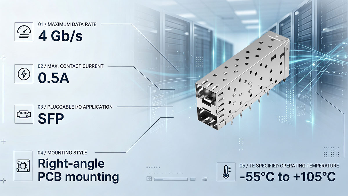
LP21AC02001 Product Overview
The LP21AC02001 is designed for applications that require two vertically stacked SFP ports. Its cage structure provides mechanical guidance for pluggable transceivers, while the press-fit termination supports through-hole PCB installation.
The main product characteristics are:
-
LINK-PP part number: LP21AC02001
-
Product type: SFP cage assembly with Integrated Connector
-
Port configuration: 2x1 stacked
-
Number of ports: 2
-
Mounting style: Through-hole, right-angle
-
PCB termination: Press-fit
-
EMI shielding: EMI springs
-
Lightpipe: Not included
-
Cage material: Nickel-plated copper alloy
-
Dimensions: 63.25mm × 14.00mm × 25.20mm
-
Operating temperature: -40°C to +85°C
-
Packaging: Tray
The model is listed as an active LINK-PP product. Its configuration provides an alternative component option for equipment designed around a 2x1 stacked SFP cage assembly.
Key Features of LP21AC02001
LP21AC02001 combines a stacked SFP port layout with a press-fit mounting structure and EMI shielding features. These characteristics are relevant when evaluating a replacement for an existing cage assembly.
2x1 stacked SFP configuration
The two vertically arranged SFP ports support high-density front-panel layouts. This configuration is useful in switches, routers, and communication equipment where multiple pluggable interfaces must fit into a limited chassis area.
Through-hole press-fit termination
The press-fit structure is designed for PCB installation without a conventional soldered termination process. Its suitability for an existing board depends on matching the pin geometry, hole dimensions, and PCB thickness requirements.
Internal and external EMI springs
EMI springs provide electrical contact between the cage and the surrounding conductive structure. Proper contact with the chassis and PCB grounding design is necessary to achieve the intended shielding performance.
Nickel-plated copper alloy construction
The cage is specified as nickel-plated copper alloy. Material and finish should be considered in relation to mechanical strength, corrosion resistance, grounding contact, and the operating environment.
Compact mechanical dimensions
The listed dimensions are 63.25mm in length, 14.00mm in width, and 25.20mm in height. These measurements provide a useful starting point for mechanical comparison, but detailed drawings are still required to verify mounting and alignment.
Why Choose LP21AC02001 as an Alternative?
LP21AC02001 offers a practical alternative for designs that use the same general 2x1 stacked SFP cage configuration as 1658391-2. Its shared mounting and shielding characteristics can simplify the initial evaluation process when an alternative component is needed.
Key considerations include:
-
Corresponding port architecture: Both models use a 2x1 stacked SFP arrangement with two ports.
-
Matching termination approach: Both use through-hole press-fit PCB termination.
-
Similar shielding concept: Both specify EMI springs.
-
No integrated lightpipe: Both product configurations are listed without an integrated lightpipe.
-
Alternative supply option: LINK-PP provides a separate product source for the LP21AC02001 model.
The two models should not be assumed to have identical electrical ratings or interchangeable PCB footprints based only on their shared configuration. The operating temperature ranges are also different. Engineers should review the detailed drawings and validate the assembly in the target hardware before approving a substitution.
1658391-2 vs. LP21AC02001 – Technical Compatibility Comparison
TE Connectivity 1658391-2 and LINK-PP LP21AC02001 share several important structural characteristics, including a 2x1 stacked SFP configuration, two ports, press-fit termination, right-angle mounting, and EMI springs. However, their published specifications are not identical, particularly for operating temperature and some electrical details.
Side-by-Side Specifications
The following table compares the main product information available from the respective manufacturer pages. Specifications not separately published for LP21AC02001 are marked accordingly rather than inferred from the TE part.
| Parameter | TE 1658391-2 | LINK-PP LP21AC02001 |
|---|---|---|
| Product type | SFP cage with integrated connector | SFP cage assembly |
| Port configuration | 2x1 stacked | 2x1 stacked |
| Number of ports | 2 | 2 |
| Number of positions | 40 | 40 |
| Maximum data rate | 4Gb/s | 4Gb/s |
| Maximum contact current | 0.5A | 0.5A |
| PCB termination | Through-hole press-fit | Through-hole press-fit |
| Mounting style | Right-angle | Right-angle |
| EMI shielding | Internal/external EMI springs | EMI springs |
| Integrated lightpipe | No | No |
| Cage material | Refer to TE product drawing | Nickel-plated copper alloy |
| Dimensions | Refer to TE product drawing | 63.25mm × 14.00mm × 25.20mm |
| Operating temperature | -55°C to +105°C | -40°C to +85°C |
| Packaging | Refer to TE product information | Tray |
The comparison shows that the two products share the main mechanical configuration and mounting approach. However, the temperature range differs, and the available LP21AC02001 product information does not separately state the same data-rate, position-count, or contact-current ratings listed by TE. These differences should be included in the engineering review.
Mechanical Compatibility and PCB Footprint
Both products use a 2x1 stacked SFP layout and through-hole press-fit mounting. This makes their mechanical configurations relevant for comparison, but it does not establish that every PCB footprint or chassis design will accept either part without modification.
The following mechanical details require verification:
-
Overall cage dimensions: Compare the full length, width, and height against the original assembly and available chassis space.
-
Press-fit pin layout: Confirm the number, location, pitch, and geometry of the pins.
-
PCB hole dimensions: Check hole diameter, plating, board thickness, and applicable tolerances.
-
Port alignment: Verify that both SFP openings align with the front-panel cutouts.
-
Mounting and retention: Check cage support, mechanical attachment, and resistance to insertion and extraction forces.
The product-level dimensions of LP21AC02001 are useful for preliminary screening. Final compatibility decisions should be based on engineering drawings and physical measurements.
Electrical and EMI Compatibility
The two assemblies specify EMI springs and a press-fit connection method, providing a similar general approach to grounding and shielding. Nevertheless, EMI performance depends on the complete installation rather than the cage alone.
For electrical and EMI validation, engineers should check:
-
Electrical contact between the cage and PCB grounding points
-
Contact between the EMI springs and the chassis or faceplate
-
Grounding continuity across the installed assembly
-
Signal-interface compatibility with the integrated connector
-
Signal integrity under the intended operating conditions
-
Shielding performance in the completed enclosure
The 1658391-2 has a published maximum data rate of 4Gb/s and a maximum contact current of 0.5A. Equivalent LP21AC02001 ratings should be confirmed from the relevant product documentation or directly with LINK-PP before they are treated as matching values.
Important Differences to Verify
The most visible published difference between the two models is their operating temperature range. TE specifies -55°C to +105°C for 1658391-2, while LP21AC02001 is listed at -40°C to +85°C.
This distinction matters for equipment exposed to low ambient temperatures, high internal temperatures, or wide temperature fluctuations. A design qualified for the full TE temperature range should not automatically be considered qualified with LP21AC02001.
Other points requiring confirmation include:
-
Detailed press-fit pin dimensions and tolerances
-
PCB footprint and hole requirements
-
Electrical ratings and signal-interface specifications
-
Cage material and surface-finish requirements
-
EMI contact performance in the target chassis
-
Mechanical durability under the expected insertion cycles
-
Applicable environmental and compliance documentation
These checks help determine whether LP21AC02001 meets the actual requirements of the original design rather than relying only on similarities in the product descriptions.
How to Verify LP21AC02001 Compatibility in Existing 1658391-2 Designs
To verify LP21AC02001 compatibility with an existing 1658391-2 design, compare the mechanical drawings, PCB footprint, press-fit pin layout, front-panel alignment, EMI grounding, and operating conditions. A prototype installation is recommended before approving the alternative for volume production.
PCB Footprint and Press-Fit Pin Layout
The PCB footprint is one of the most important factors in evaluating a press-fit cage replacement. Even when two assemblies share the same port configuration, differences in pin geometry or hole requirements can prevent correct installation.
Compare the following details in the original and alternative product drawings:
-
Pin count and pin arrangement
-
Pin pitch and center-to-center spacing
-
Pin dimensions and press-fit contact geometry
-
PCB hole diameter and tolerance
-
PCB thickness and plating requirements
-
Cage locating features and mechanical supports
The press-fit interface must provide the required mechanical retention and electrical connection without damaging the PCB. If the pin layout or hole specifications differ, the existing board may require redesign or additional validation.
SFP Port and Chassis Dimensions
The cage must align with both the PCB and the equipment's front panel. Incorrect dimensions can cause transceiver insertion problems, port misalignment, or interference with adjacent components.
For LP21AC02001, the listed overall dimensions are 63.25mm × 14.00mm × 25.20mm. Compare these values with the available space in the existing design, then verify the detailed drawing for the exact location of the port openings and mounting features.
Important checks include:
-
Distance between the upper and lower SFP ports
-
Port opening dimensions and alignment
-
Front-panel cutout position
-
Clearance from adjacent cages and components
-
Cage height relative to the PCB
-
Space for transceiver insertion and removal
A dimensional match at the overall level is not sufficient. The position of each mounting and alignment feature must also be confirmed.
EMI Shielding and Thermal Requirements
EMI shielding and thermal suitability should be evaluated in the installed hardware, not only from the component description. Both assemblies list EMI springs, but the actual shielding result depends on the contact surfaces, grounding design, and chassis construction.
During evaluation, check:
-
Whether the EMI springs make consistent contact with the chassis
-
Whether the cage has a reliable grounding path
-
Whether the front-panel structure maintains electrical continuity
-
Whether the installed cage meets the system's EMI requirements
-
Whether the operating temperature range covers the equipment's actual environment
The temperature difference deserves particular attention. LP21AC02001 is listed for -40°C to +85°C, whereas 1658391-2 is specified for -55°C to +105°C. Applications that require operation outside the LP21AC02001 range need further review before substitution.
Prototype and Assembly Validation
A prototype test is the most practical way to identify mechanical or electrical issues before production approval. It allows engineers to evaluate the actual fit and performance of LP21AC02001 in the target board and chassis.
A typical validation process includes:
-
Review product drawings: Compare the original and alternative cage drawings, including pin locations, dimensions, and mounting details.
-
Inspect the PCB footprint: Confirm that the existing board meets the press-fit hole and tolerance requirements.
-
Install a sample assembly: Check insertion force, alignment, mechanical retention, and cage stability.
-
Test SFP module insertion: Confirm that representative SFP transceivers can be inserted and removed correctly.
-
Verify grounding and EMI: Check contact continuity and conduct the required system-level EMI tests.
-
Evaluate operating conditions: Confirm that the product's temperature rating is suitable for the equipment environment.
-
Document the results: Record dimensional checks, assembly observations, and electrical or environmental test results.
Successful prototype validation provides a stronger basis for approving LP21AC02001 than a part-number comparison alone.
Typical Applications of the 1658391-2 Compatible LP21AC02001
LP21AC02001 is intended for SFP hardware designs that use a 2x1 stacked cage configuration, press-fit PCB termination, and EMI spring shielding. Its mechanical arrangement is relevant to network and communication equipment that requires two vertically stacked SFP interfaces.

Ethernet Switches and Routers
Ethernet switches and routers often use multiple SFP ports to support fiber or copper connectivity across different network segments. A stacked cage arrangement helps increase front-panel port density while keeping the PCB layout compact.
LP21AC02001 can be evaluated for switch and router designs that use a corresponding 2x1 SFP cage structure. Before installation, engineers should confirm the original cage footprint, port spacing, front-panel dimensions, and electrical interface requirements.
Typical equipment categories include:
-
Enterprise Ethernet switches
-
Aggregation switches
-
Access routers
-
Network interface platforms
-
Fiber access equipment
Data Center and Telecom Equipment
Data center and telecommunications hardware often requires high-density interfaces, reliable mechanical retention, and effective EMI shielding. A stacked SFP cage can support compact equipment layouts where two ports share a vertical front-panel area.
LP21AC02001 may be considered for corresponding designs in:
-
Data center networking equipment
-
Telecom access and aggregation systems
-
Optical communication platforms
-
Network transport equipment
-
Communication infrastructure hardware
The suitability of the assembly depends on the product's electrical and environmental requirements. In particular, the -40°C to +85°C operating range should be checked against the system qualification requirements.
Industrial and Embedded Networking
Industrial and embedded networking equipment can operate in environments with greater temperature variation, vibration, and limited installation space. Mechanical retention, grounding, and operating temperature are therefore important selection factors.
For these applications, LP21AC02001 should be evaluated against:
-
The equipment's minimum and maximum operating temperatures
-
Expected vibration and mechanical stress
-
PCB thickness and press-fit requirements
-
Chassis grounding and EMI performance
-
Transceiver insertion and extraction requirements
-
Applicable environmental qualification standards
Its 2x1 stacked configuration may suit compact embedded network designs, but applications requiring operation below -40°C or above +85°C need additional consideration.
Why Consider LINK-PP LP21AC02001? Stock Availability and Supply Advantages
LINK-PP provides LP21AC02001 as an alternative source for applications using the TE Connectivity 1658391-2 SFP cage configuration. The model offers a corresponding 2x1 stacked layout, press-fit termination, and EMI springs, giving engineering and procurement teams another component option to evaluate.
Ready Stock and Product Availability
Component availability can affect production schedules, maintenance plans, and hardware deployment timelines. Having an alternative source for a required SFP cage assembly can help reduce dependence on a single supply channel.
LINK-PP lists LP21AC02001 on its product website. Current stock quantities, pricing, and lead times should be confirmed through the product page or sales team, as inventory and fulfillment conditions may change.
For product details and availability, visit the LINK-PP LP21AC02001 product page.
A Flexible Alternative for Existing Designs
LP21AC02001 provides another option for designs based on a 2x1 stacked SFP cage assembly. Its corresponding port configuration, right-angle mounting, press-fit termination, and EMI springs make it relevant to replacement evaluations involving 1658391-2.
Before confirming a substitution, engineering teams should review:
-
Mechanical drawing compatibility
-
PCB footprint and press-fit pin dimensions
-
Electrical and signal-interface requirements
-
EMI grounding and shielding performance
-
Operating temperature requirements
-
Prototype test results
This process helps ensure that the selected alternative meets the requirements of the actual application.
LINK-PP SFP Cage and Connector Portfolio
In addition to LP21AC02001, LINK-PP provides SFP cage and connector products in different port configurations and mounting arrangements. The portfolio can support hardware designs with varying front-panel layouts, PCB structures, and shielding requirements.
When reviewing related models, consider the following product characteristics:
-
SFP or other pluggable interface type
-
Single-port or stacked port configuration
-
Number of ports and port matrix
-
Through-hole or other PCB termination method
-
Right-angle or other mounting arrangement
-
EMI spring configuration
-
Lightpipe availability
-
Cage dimensions and operating temperature
Selecting the correct configuration at the beginning of the design review can reduce mechanical redesign and qualification work.
Conclusion
LINK-PP LP21AC02001 is a compatible alternative to TE Connectivity 1658391-2 for corresponding 2x1 stacked SFP cage applications. Both models share key structural characteristics, including two vertically arranged SFP ports, through-hole press-fit termination, right-angle mounting, and EMI springs. The main published difference to consider is the operating temperature range, along with electrical and detailed mechanical specifications that require confirmation.
Key points to remember:
-
TE 1658391-2: A 2x1 stacked SFP cage assembly with an integrated connector, 40 positions, and a maximum data rate of 4Gb/s.
-
LINK-PP LP21AC02001: A 2x1 stacked SFP cage with press-fit mounting, EMI springs, nickel-plated copper alloy construction, and dimensions of 63.25mm × 14.00mm × 25.20mm.
-
Compatibility checks: Confirm the PCB footprint, press-fit pin layout, chassis alignment, EMI grounding, electrical requirements, and operating temperature before approving a replacement.
-
Supply option: LINK-PP provides LP21AC02001 as an alternative component source, with current availability and quotation details available through its product page.
For projects evaluating a 1658391-2 compatible replacement, LINK-PP offers LP21AC02001 as an alternative to consider. Visit the LINK-PP Official Store to review the product details and request a quotation. Standard stock items are covered by a 15-day no-reason return and exchange policy, and LINK-PP covers return shipping for quality-related issues. Contact the LINK-PP team for current availability and project-specific product information.