


































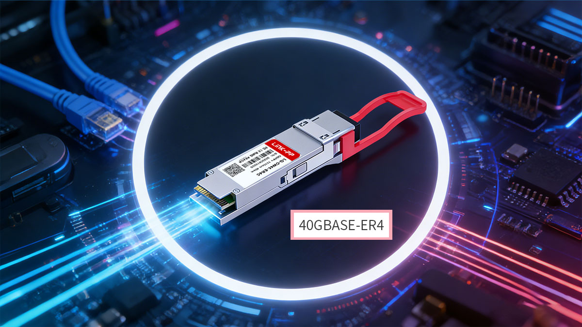
40GBASE-ER4 is a long-reach 40GbE optical standard that delivers 40Gbps transmission over single-mode fiber up to 40km using QSFP+ transceiver. It achieves this reach by multiplexing four CWDM optical lanes into a duplex LC fiber interface, allowing long-distance connectivity without requiring complex DWDM systems.
A typical 40GBASE-ER4 module converts four ~10Gbps electrical input channels into four CWDM optical signals and combines them for transmission over a single fiber pair. At the receiving end, the optical signal is demultiplexed back into four electrical channels to restore the 40Gbps data stream. This architecture is compliant with IEEE802.3ba and QSFP MSA specifications and is widely used in long-reach 40GbE deployments.
The CWDM wavelengths used in 40GBASE-ER4 are centered around 1271nm, 1291nm, 1311nm, and 1331nm, following the ITU-T wavelength grid and optimized for transmission over single-mode fiber. Combined with APD receiver technology and long-reach optical budgets, the standard supports stable links across metro distances and extended campus networks.
40GBASE-ER4 is typically deployed in scenarios where 10km or 20km optics are insufficient but a full DWDM transport layer is unnecessary. Common use cases include:
- Metro or inter-building data center interconnect
- Long-reach switch-to-router links
- Enterprise or campus backbone connections
- Carrier aggregation or access networks
This guide provides a structured technical overview of 40GBASE-ER4, covering its architecture, key specifications, optical characteristics, interfaces, and deployment considerations to help engineers understand when and how to use this long-distance 40G optical technology.
? What Is 40GBASE-ER4?
40GBASE-ER4 is a long-reach 40GbE optical interface standard that uses four CWDM wavelengths over single-mode fiber to support transmission distances up to 40km. It is defined under IEEE 802.3ba and typically implemented in QSFP+ transceivers for high-bandwidth, long-distance Ethernet links.
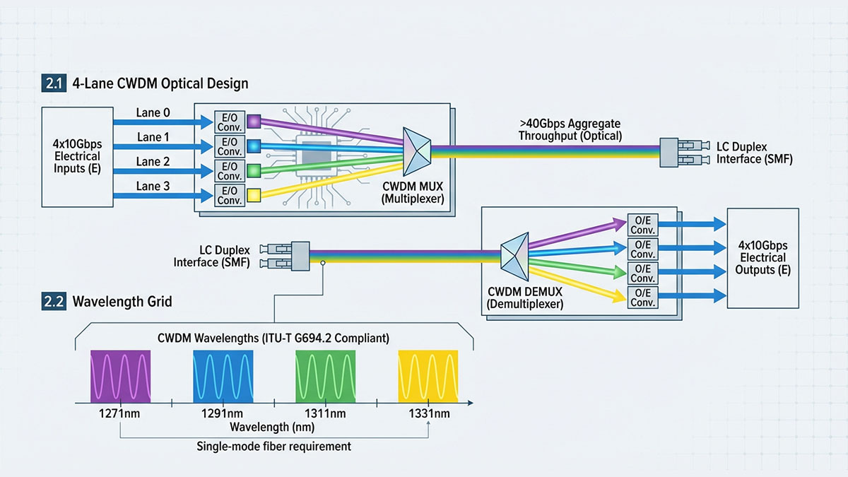
At a functional level, 40GBASE-ER4 transmits data by splitting a 40Gbps signal into four parallel electrical lanes of approximately 10Gbps each. These lanes are converted into four CWDM optical signals, multiplexed onto a single duplex LC fiber pair for transmission, and then demultiplexed back into electrical lanes at the receiver. This parallel-lane CWDM architecture allows 40Gbps throughput while maintaining long-reach optical performance over standard single-mode fiber.
Core Characteristics of 40GBASE-ER4
40GBASE-ER4 is primarily defined by its 40km reach, CWDM wavelength scheme, and QSFP+ form factor compatibility.
| Parameter | Typical Value | Notes |
|---|---|---|
| Data rate | 40Gbps | 4×~10Gbps lanes |
| Max distance | 40km | Over single-mode fiber |
| Wavelengths | 1271–1331nm | CWDM grid |
| Connector | Duplex LC | Standard SMF interface |
| Form factor | QSFP+ | MSA compliant |
These characteristics position 40GBASE-ER4 between shorter-reach optics such as SR4 transceiver or LR4 transceiver and more complex long-haul DWDM solutions. It enables long-distance Ethernet connectivity while remaining compatible with standard QSFP+ switch and router ports.
Wavelength and Optical Design
40GBASE-ER4 uses four CWDM wavelengths to achieve long-distance transmission without requiring dense wavelength systems.
| Lane | Center Wavelength | Function |
|---|---|---|
| L0 | 1271nm | Tx/Rx |
| L1 | 1291nm | Tx/Rx |
| L2 | 1311nm | Tx/Rx |
| L3 | 1331nm | Tx/Rx |
These wavelengths follow the ITU-T CWDM grid and are multiplexed into a single optical path for transmission over single-mode fiber. APD receivers and long-reach optical budgets allow stable operation across extended distances up to 40km under typical conditions.
Typical Role in 40G Networks
40GBASE-ER4 is used when 40GbE links must extend beyond campus or building distances but do not require full DWDM transport systems.
Common deployment scenarios include:
- Metro data center interconnect
- Long-distance switch-to-router links
- Campus backbone connections
- Carrier aggregation or access networks
In modern network design, 40GBASE-ER4 remains a practical option for extending existing 40GbE infrastructure across longer distances while maintaining compatibility with QSFP+ hardware platforms.
? 40GBASE-ER4 Module Architecture
A 40GBASE-ER4 module uses a 4-lane CWDM MUX/DEMUX architecture to convert four ~10Gbps electrical signals into a single 40Gbps optical link over single-mode fiber. This parallel-lane design enables long-distance transmission while maintaining compatibility with QSFP+ electrical interfaces and standard duplex LC fiber connections.
At the transmitter side, four independent electrical input lanes are converted into four optical wavelengths. These wavelengths are multiplexed into one optical output and transmitted over a single fiber pair. At the receiver, the process is reversed: the incoming optical signal is demultiplexed into four wavelengths and converted back into four electrical lanes for the host system. This architecture allows the module to deliver full 40Gbps throughput while supporting extended reach up to 40km.
4-Lane CWDM Transmission Structure
QSFP ER4 relies on four CWDM optical lanes to achieve long-reach 40Gbps transmission without requiring dense wavelength systems.
| Lane | Center Wavelength | Role in Transmission |
|---|---|---|
| Lane 0 | 1271nm | Optical TX/RX |
| Lane 1 | 1291nm | Optical TX/RX |
| Lane 2 | 1311nm | Optical TX/RX |
| Lane 3 | 1331nm | Optical TX/RX |
These wavelengths follow the CWDM grid and are multiplexed into a single optical path. By using spaced CWDM wavelengths rather than tightly packed DWDM channels, the design balances optical performance, cost, and implementation complexity for metro-scale links.
This four-lane structure also aligns with the electrical architecture of QSFP+ ports, which typically operate with four parallel data lanes internally. As a result, no external gearbox is required for standard 40GbE operation.
Optical and Electrical Signal Flow
The internal signal path of a 40GBASE-ER4 module follows a parallel-to-serial optical conversion model.
Signal flow overview:
- Host ASIC outputs 4× electrical lanes (~10Gbps each)
- Electrical lanes drive optical transmitters
- Four CWDM optical signals are multiplexed
- Optical signal travels over single-mode fiber
- Receiver demultiplexes wavelengths
- Optical signals convert back to electrical lanes
- Host system receives restored 40Gbps data
This architecture minimizes dispersion impact and enables stable long-distance transmission using standard single-mode fiber infrastructure.
Key Hardware Components
Several core optical and electrical components enable long-reach ER4 performance.
| Component | Function | Purpose |
|---|---|---|
| CWDM lasers | Generate optical wavelengths | Multi-lane transmission |
| Optical MUX/DEMUX | Combine/split wavelengths | Single fiber pair operation |
| APD receiver | Detect low optical signals | Long-reach sensitivity |
| DSP/electrical interface | Lane alignment | Signal integrity |
| DDM interface | Monitoring | Diagnostics and control |
The use of APD receivers improves sensitivity, which is essential for maintaining signal quality over distances up to 40km. Meanwhile, the QSFP+ form factor integrates optical, electrical, and diagnostic functions into a compact pluggable module.
Form Factor and Interface Design
40GBASE-ER4 modules are typically implemented in QSFP+ form factor with duplex LC optical interfaces and a 38-pin electrical connector.
| Interface Type | Specification | Notes |
|---|---|---|
| Form factor | QSFP+ | MSA compliant |
| Optical connector | Duplex LC | Single-mode fiber |
| Electrical lanes | 4 TX / 4 RX | Parallel interface |
| Supply voltage | +3.3V | Single supply |
| Control interface | 2-wire serial | Monitoring & control |
The QSFP+ form factor ensures compatibility with standard switch and router ports while providing integrated digital diagnostics, control signals, and hot-plug capability.
Why This Architecture Is Used
The 4-lane CWDM architecture of 40GBASE-ER4 provides a practical balance between reach, complexity, and compatibility.
Key design advantages:
- Supports 40km transmission without DWDM systems
- Uses standard single-mode fiber
- Maintains QSFP+ port compatibility
- Enables manageable optical budgets
- Allows per-lane diagnostics and control
This architecture makes 40GBASE-ER4 suitable for metro and long-reach enterprise links where shorter-reach 40G optics cannot meet distance requirements but higher-cost coherent or DWDM solutions are unnecessary.
? Key Specifications of 40GBASE-ER4
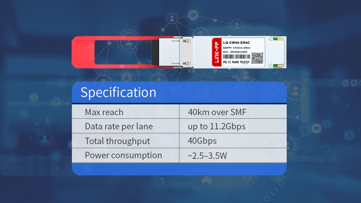
40GBASE-ER4 is defined by its 40Gbps throughput, 40km transmission reach, four CWDM wavelength, and QSFP+ electrical interface operating on a single +3.3V power supply. These specifications determine its role as a long-reach 40GbE optical solution for metro and extended data center interconnect links.
Understanding the key electrical, optical, and environmental parameters helps ensure proper compatibility, link budgeting, and deployment planning.
Core Performance Specifications
The primary performance profile of 40GBASE-ER4 centers on long-distance transmission over single-mode fiber with four parallel lanes.
| Parameter | Typical Value | Notes |
|---|---|---|
| Aggregate data rate | 40Gbps | 4× ~10Gbps lanes |
| Reach | up to 40km | Single-mode fiber |
| Wavelengths | 1271–1331nm | CWDM grid |
| Optical connector | Duplex LC | SMF interface |
| Form factor | QSFP+ | MSA compliant |
These parameters define the baseline interoperability expectations for 40GBASE-ER4 modules used in switches, routers, and transport equipment.
Electrical Characteristics
40GBASE-ER4 modules operate using a single +3.3V power supply and support standard QSFP+ electrical signaling with four transmit and four receive lanes.
| Electrical Parameter | Typical Value | Notes |
|---|---|---|
| Supply voltage | +3.3V | Single supply |
| Power consumption | ~2.5–3.5W | Depends on vendor design |
| Data rate per lane | ~10–11.2Gbps | Parallel lanes |
| Inter-channel skew | ≤150ps | Lane alignment |
| Initialization time | ≤2s | Power-on readiness |
Power consumption is typically higher than short-reach modules due to the longer optical reach and use of higher-sensitivity receivers. Thermal planning should account for this in dense port environments.
Optical Transmission Specifications
Optical performance parameters determine whether a 40GBASE-ER4 link can reliably operate over long distances.
| Optical Parameter | Typical Range | Purpose |
|---|---|---|
| Launch power (per lane) | −3 to +5dBm | Transmit strength |
| Receiver sensitivity | down to ~−21dBm | Long-reach detection |
| Extinction ratio | ≥3.5dB | Signal quality |
| TDP (per lane) | ~2–3dB | Dispersion tolerance |
| Optical return loss | ≥12–20dB | Reflection control |
These optical characteristics enable stable operation across 40km links while maintaining acceptable signal integrity and error performance.
Wavelength Assignment
40GBASE-ER4 uses four CWDM wavelengths centered between 1271nm and 1331nm to carry parallel optical lanes.
| Lane | Center Wavelength | Function |
|---|---|---|
| Lane 0 | 1271nm | TX/RX |
| Lane 1 | 1291nm | TX/RX |
| Lane 2 | 1311nm | TX/RX |
| Lane 3 | 1331nm | TX/RX |
These wavelengths follow the CWDM grid and are multiplexed into a single fiber pair, allowing efficient long-distance transmission without dense wavelength multiplexing systems.
Environmental and Operating Conditions
40GBASE-ER4 modules are designed for standard commercial operating environments with defined thermal and electrical limits.
| Parameter | Range | Notes |
|---|---|---|
| Operating temperature | 0–70°C | Commercial range |
| Storage temperature | −40–85°C | Non-operating |
| Supply tolerance | ~3.13–3.47V | Voltage range |
| Max power dissipation | ~3.5W | Thermal planning |
Maintaining operation within these limits ensures stable optical output and receiver sensitivity across long-distance links.
Digital Diagnostics and Control
Most 40GBASE-ER4 modules include digital diagnostic monitoring (DDM) via a 2-wire serial interface for real-time status tracking.
| Monitoring Parameter | Function |
|---|---|
| Temperature | Thermal status |
| Supply voltage | Power stability |
| Tx optical power | Output monitoring |
| Rx optical power | Link margin |
| Alarm flags | Fault detection |
These monitoring capabilities allow network operators to track link health, identify degradation, and perform predictive maintenance.
? Interface and Hardware Design
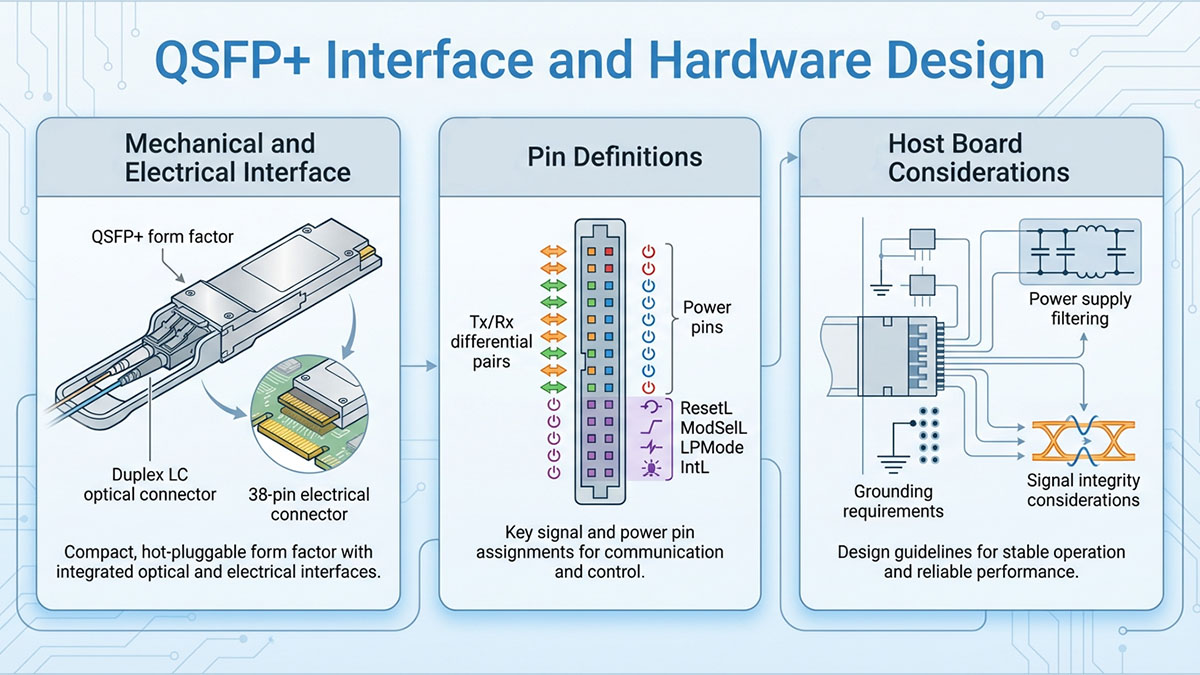
40GBASE-ER4 modules are built on the QSFP+ form factor and provide a duplex LC optical interface, a 38-pin electrical connector, and a 2-wire management interface for control and diagnostics. This standardized hardware design ensures interoperability with common 40GbE switch and router ports while supporting long-reach optical transmission.
Understanding the electrical interface, pin functions, and hardware control signals is important for system integration, host board design, and operational stability.
QSFP+ Form Factor and Physical Interface
40GBASE-ER4 typically uses the QSFP+ pluggable form factor with a duplex LC connector for single-mode fiber links.
| Interface Element | Specification | Purpose |
|---|---|---|
| Form factor | QSFP+ | 40G pluggable module |
| Optical connector | Duplex LC | SMF transmission |
| Electrical connector | 38-pin edge | Host interface |
| Fiber type | Single-mode fiber | Long reach |
| Hot-plug support | Yes | Live insertion/removal |
The QSFP+ mechanical design allows hot-swapping and high port density, making it suitable for switches, routers, and transport equipment that require long-reach 40GbE connectivity.
Electrical Lane Interface
A 40GBASE-ER4 module interfaces with the host system using four transmit lanes and four receive lanes at approximately 10Gbps each.
| Signal Group | Direction | Function |
|---|---|---|
| TX lanes (×4) | Host → module | Electrical input data |
| RX lanes (×4) | Module → host | Electrical output data |
| Reference clock | Host ↔ module | Timing alignment |
| Ground pins | — | Signal stability |
| Power pins | Host → module | +3.3V supply |
These parallel electrical lanes align with the internal CWDM optical architecture, allowing direct mapping between electrical and optical channels without requiring external gearboxes in standard 40GbE applications.
Signal integrity considerations:
- Controlled impedance differential pairs
- Short trace routing
- Proper grounding
- Power supply filtering
Power and Thermal Design
40GBASE-ER4 modules operate from a single +3.3V power supply and typically consume up to around 3.5W due to long-reach optical components.
| Parameter | Typical Value | Design Impact |
|---|---|---|
| Supply voltage | +3.3V | Standard QSFP+ |
| Power consumption | ~2.5–3.5W | Thermal planning |
| Supply current | up to ~1A | Power rail design |
| Operating temp | 0–70°C | Cooling required |
Because ER4 modules consume more power than short-reach optics, adequate airflow and thermal management are necessary in high-density switch environments.
Control and Management Signals
40GBASE-ER4 modules include several low-speed control and status pins used for monitoring, reset, and power management.
| Signal | Direction | Function |
|---|---|---|
| ModPrsL | Module → host | Module present |
| ResetL | Host → module | Hardware reset |
| IntL | Module → host | Interrupt/alarms |
| LPMode | Host → module | Low-power mode |
| ModSelL | Host → module | Module select |
These signals allow the host system to manage module operation, detect faults, and reduce power consumption when needed.
Typical control functions include:
- Resetting the module
- Detecting insertion/removal
- Triggering alarms
- Entering low-power mode
- Enabling diagnostics access
Digital Diagnostics Interface
40GBASE-ER4 modules support digital diagnostics monitoring through a 2-wire serial interface compatible with standard QSFP+ management protocols.
| Interface | Function |
|---|---|
| SCL/SDA | Serial communication |
| Memory map | EEPROM + diagnostics |
| Monitoring | Temp, voltage, power |
| Interrupt flags | Fault reporting |
This interface enables the host system to read module status and performance metrics in real time. It also allows channel-level monitoring and alarm handling, which is especially useful for long-distance links where optical margins must be closely tracked.
Host Board Design Considerations
Proper host hardware design ensures stable operation and signal integrity when deploying 40GBASE-ER4 modules.
Key considerations:
- Provide stable +3.3V power rails
- Implement recommended filtering for Vcc pins
- Maintain differential impedance control
- Ensure adequate airflow for thermal dissipation
- Support I²C communication for diagnostics
- Validate signal timing and skew
For long-reach modules, optical link stability is strongly influenced by electrical signal quality and power stability at the host interface.
? Digital Diagnostics Monitoring (DDM)
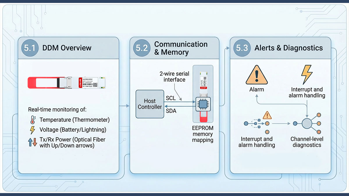
40GBASE-ER4 modules typically support Digital Diagnostics Monitoring (DDM) through a 2-wire serial interface, enabling real-time visibility into optical power, temperature, voltage, and alarm conditions. This monitoring capability is essential for long-reach links where optical margins and environmental stability directly affect transmission reliability.
DDM allows the host system to read module status data, detect faults, and track performance trends without interrupting traffic. For 40km optical links, this visibility is critical for proactive maintenance and link validation.
What DDM Monitors in 40GBASE-ER4
DDM provides continuous monitoring of key electrical and optical parameters to ensure stable operation.
| Parameter | Monitoring Purpose | Operational Value |
|---|---|---|
| Module temperature | Thermal status | Prevent overheating |
| Supply voltage | Power stability | Detect power issues |
| Tx optical power | Output level | Verify launch power |
| Rx optical power | Received signal | Check link margin |
| Alarm flags | Fault detection | Rapid troubleshooting |
These metrics allow network operators to verify whether a long-distance link is operating within the expected optical budget and environmental limits.
For example:
- Low Rx power may indicate fiber loss or connector contamination
- High temperature may signal airflow issues
- Voltage deviation may indicate host power instability
Management Interface and Memory Structure
DDM data is accessed through a standard 2-wire serial interface that provides both real-time monitoring and stored module information.
| Interface Element | Function |
|---|---|
| 2-wire serial bus | Communication with host |
| Memory map | Stores ID and diagnostics |
| Interrupt flags | Alert conditions |
| Threshold values | Alarm triggers |
The memory space is typically divided into lower and upper pages:
- Lower page: real-time status and alarms
- Upper pages: module ID, thresholds, calibration data
This structure allows the host system to quickly read critical status information while still accessing extended configuration and historical data when needed.
Alarm and Interrupt Handling
DDM supports threshold-based alarms and interrupt signaling to notify the host system of abnormal conditions.
Common alarm triggers include:
- Rx power below threshold
- Tx power out of range
- Over-temperature condition
- Voltage deviation
- Loss of signal (LOS)
When a monitored parameter exceeds a defined threshold, the module asserts an interrupt signal. The host system can then read the diagnostic registers to determine which channel and parameter triggered the event.
This mechanism enables:
- Fast fault detection
- Channel-level troubleshooting
- Automated monitoring systems
- Preventive maintenance
Deployment Best Practices
Using DDM effectively improves reliability and simplifies troubleshooting in 40GBASE-ER4 deployments.
Recommended practices:
- Check Tx/Rx power during link commissioning
- Set monitoring thresholds in the host system
- Monitor temperature in high-density chassis
- Track long-term optical power trends
- Investigate alarms promptly
In large networks, DDM data is often integrated into network management systems, allowing automated monitoring of optical links across multiple sites.
? Operating Environment and Reliability
40GBASE-ER4 modules are designed to operate reliably in standard commercial networking environments, with defined temperature, power, and environmental limits that ensure stable 40km transmission over single-mode fiber. Staying within these operating conditions is essential to maintain optical performance, receiver sensitivity, and long-term link stability.
Because ER4 modules are used for long-distance transmission and typically consume more power than short-reach optics, environmental control and hardware reliability considerations are particularly important.
Operating Temperature and Environmental Limits
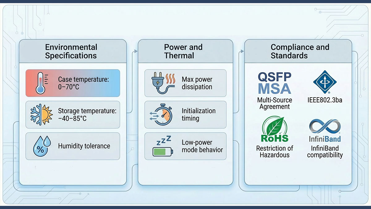
Most 40GBASE-ER4 modules support commercial operating conditions ranging from 0°C to 70°C case temperature, with wider storage tolerances.
| Parameter | Typical Range | Operational Impact |
|---|---|---|
| Operating temperature | 0–70°C | Normal operation |
| Storage temperature | −40–85°C | Non-operating storage |
| Relative humidity | up to ~85% | Non-condensing |
| Operating altitude | Standard DC range | Cooling considerations |
Operating outside the recommended temperature range can affect laser stability, receiver sensitivity, and overall link margin. Maintaining proper airflow and thermal control is therefore critical in high-density switch environments.
Power and Thermal Stability
40GBASE-ER4 modules typically operate from a single +3.3V power supply and can dissipate up to around 3.5W, requiring adequate thermal management.
| Parameter | Typical Value | Design Consideration |
|---|---|---|
| Supply voltage | +3.3V | Stable power rail |
| Voltage tolerance | ~3.13–3.47V | Regulation required |
| Power consumption | ~2.5–3.5W | Higher than SR optics |
| Max current | ~1A | Power budget planning |
Higher power consumption is primarily due to long-reach optical transmitters and high-sensitivity receivers. In dense switch chassis, insufficient cooling can lead to elevated module temperature, which may reduce optical output stability or shorten component lifespan.
Recommended practices:
- Ensure front-to-back airflow
- Avoid blocking ventilation
- Monitor temperature via DDM
- Validate thermal design in high-port-count systems
Initialization and Reset Behavior
40GBASE-ER4 modules follow defined initialization and reset timing requirements to ensure stable startup and operation.
| Timing Parameter | Typical Value | Function |
|---|---|---|
| Power-on initialization | up to ~2s | Full readiness |
| Reset duration | microseconds–ms | Hardware reset |
| Data ready time | up to ~2s | Monitoring ready |
| Low-power mode entry | <1ms | Reduced consumption |
After insertion or power-on, the module requires a short initialization period before all functions and diagnostics are available. During this time, the host system should allow for proper startup sequencing.
Reliability Features
Several hardware and design features support long-term reliability in 40GBASE-ER4 deployments.
| Feature | Purpose | Benefit |
|---|---|---|
| APD receiver | High sensitivity | Long-distance stability |
| CWDM wavelengths | Lower dispersion | Reliable transmission |
| Digital diagnostics | Real-time monitoring | Early fault detection |
| QSFP+ MSA compliance | Interoperability | Platform compatibility |
| RoHS compliance | Environmental safety | Regulatory adherence |
Long-distance optical links are more sensitive to attenuation and environmental changes than short-reach links. Reliable hardware design and monitoring features help maintain consistent performance over time.
Common Reliability Risks and Mitigation
Environmental and operational factors can affect long-reach optical performance if not properly managed.
Potential risks:
- Elevated temperature in dense chassis
- Dirty or damaged fiber connectors
- Excessive fiber loss
- Power supply instability
- Improper cable handling
Mitigation strategies:
- Maintain clean fiber interfaces
- Verify optical budget during deployment
- Monitor DDM alarms
- Ensure proper airflow
- Use stable power sources
Regular monitoring and preventive maintenance significantly improve long-term reliability for 40GBASE-ER4 links.
? Typical Applications of 40GBASE-ER4
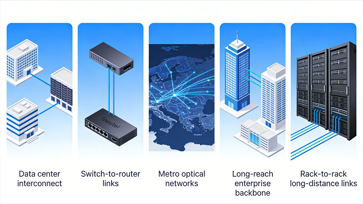
40GBASE-ER4 is primarily used for long-distance 40GbE links up to 40km where standard SR4 or LR4 optics cannot meet reach requirements but a full DWDM transport system is unnecessary. Its CWDM-based QSFP+ design makes it suitable for metro, campus, and extended data center interconnect scenarios that require stable high-bandwidth transmission over single-mode fiber.
Because it supports long reach using a duplex LC interface and standard QSFP+ ports, 40GBASE-ER4 is often deployed in environments that need predictable optical performance with manageable infrastructure complexity.
Data Center Interconnect (DCI)
40GBASE-ER4 is commonly used for metro-scale data center interconnect links between facilities separated by several kilometers to tens of kilometers.
| Use Case | Distance Range | Why ER4 Fits |
|---|---|---|
| Inter-building DCI | 5–20km | Beyond LR4 reach |
| Metro DCI | 20–40km | Stable long-reach optics |
| Backup site links | up to 40km | Reliable bandwidth |
| Regional aggregation | 10–30km | Simple architecture |
In these deployments, ER4 enables direct 40GbE connectivity without requiring external wavelength multiplexing systems, simplifying network architecture while maintaining sufficient optical margin for metro distances.
Campus and Enterprise Backbone
Large campus networks use 40GBASE-ER4 to extend high-capacity backbone links across geographically distributed buildings.
Typical scenarios:
- University campus networks
- Industrial parks
- Financial districts
- Multi-building enterprise environments
Deployment characteristics:
- Single-mode fiber infrastructure
- Long building-to-building runs
- Aggregation layer connectivity
- High reliability requirements
ER4 modules allow network operators to maintain 40GbE speeds across extended campus environments without redesigning the optical transport layer.
Switch-to-Router and Core Links
40GBASE-ER4 is used for long-reach connections between aggregation switches, core routers, and transport equipment.
| Connection Type | Reason for Using ER4 |
|---|---|
| Core-to-aggregation | Extended reach |
| Router-to-router | High bandwidth |
| Aggregation rings | Metro distance |
| Edge-to-core uplinks | Stable optics |
These links often span multiple buildings or central offices where distances exceed the capability of shorter-reach optics.
Metro and Access Network Integration
In metro or service provider environments, 40GBASE-ER4 can support aggregation and access transport links across urban fiber infrastructure.
Typical use cases:
- Metro aggregation rings
- Access network uplinks
- Inter-POP connectivity
- Regional switching nodes
Because ER4 uses CWDM wavelengths within a single module, it avoids the complexity of deploying full DWDM equipment for moderate-distance links.
? 40GBASE-ER4 vs Other 40G Optics
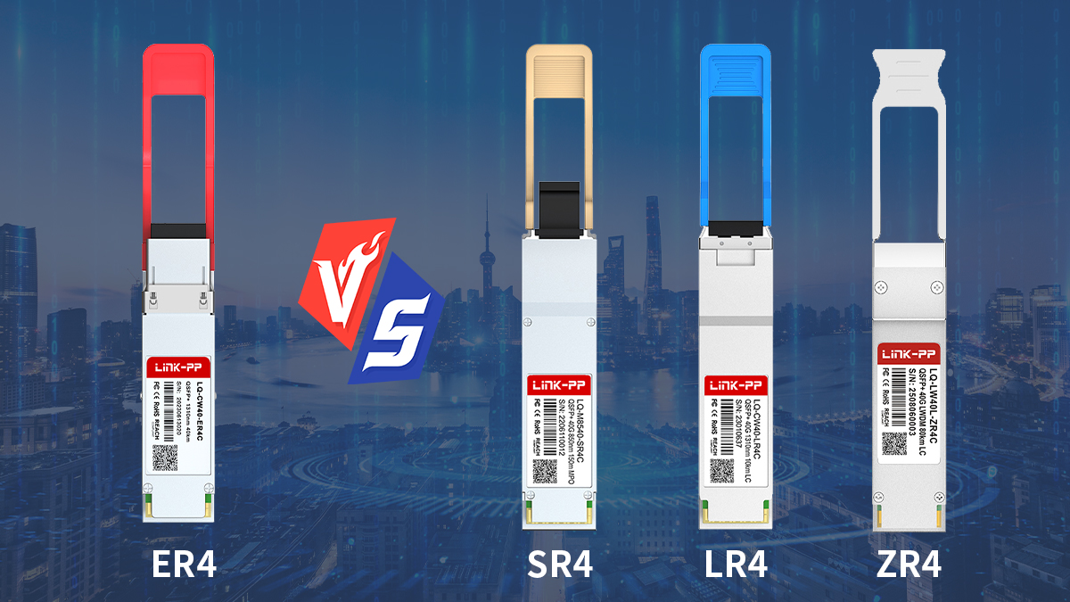
40GBASE-ER4 is the preferred 40GbE optical option for distances up to 40km, positioned between shorter-reach LR4 optics and more complex long-haul DWDM or ZR solutions. Choosing the correct 40G optic depends primarily on distance, fiber type, power budget, and deployment complexity.
Understanding how ER4 compares with other common 40G modules helps determine when it is the most appropriate choice.
ER4 vs SR4
The main difference between ER4 and SR4 is transmission distance and fiber type: SR4 is for short multimode links, while ER4 is for long single-mode links up to 40km.
| Parameter | 40GBASE-ER4 | 40GBASE-SR4 |
|---|---|---|
| Max distance | up to 40km | up to ~100–150m |
| Fiber type | Single-mode | Multimode fiber (MPO) |
| Wavelength | CWDM 1271–1331nm | 850nm |
| Connector | Duplex LC | MPO/MTP |
| Typical use | Metro/campus | Inside data center |
SR4 is typically used inside data centers for short-reach links. ER4 is chosen when the link extends far beyond building-level distances and requires single-mode fiber.
ER4 vs LR4
ER4 extends the reach of LR4 from about 10km to up to 40km while maintaining the same basic QSFP+ form factor and CWDM architecture.
| Parameter | 40GBASE-ER4 | 40GBASE-LR4 |
|---|---|---|
| Max distance | up to 40km | up to ~10km |
| Fiber type | Single-mode | Single-mode |
| Wavelength scheme | CWDM | CWDM |
| Power consumption | Higher | Lower |
| Deployment | Metro/campus | Campus/DCI short reach |
Both ER4 and LR4 use four CWDM wavelengths and duplex LC connectors, but ER4 includes higher optical output power and more sensitive receivers to support longer distances. As a result, ER4 generally consumes more power and requires tighter optical budget planning.
Use LR4 when:
- Distance ≤10km
- Lower power is preferred
- Inside campus or metro edge
Use ER4 when:
- Distance >10km
- Up to 40km required
- Metro interconnect
ER4 vs ZR4 or DWDM Solutions
Compared with ZR4 or DWDM transport optics, ER4 offers simpler deployment for moderate long-distance links but with shorter maximum reach.
| Parameter | 40GBASE-ER4 | 40G ZR/DWDM |
|---|---|---|
| Max distance | up to 40km | 80km+ |
| Wavelength | CWDM | DWDM |
| Complexity | Moderate | High |
| Cost per link | Lower | Higher |
| Typical use | Metro DCI | Long-haul transport |
ZR or DWDM optics are typically used for carrier or long-haul transport networks requiring distances beyond 40km. ER4 is used when reach requirements are significant but still within metro-scale limits.
? Integration and Deployment Tips of 40GBASE ER4
Successful deployment of 40GBASE-ER4 links depends on proper optical budget planning, clean single-mode fiber infrastructure, stable power and thermal conditions, and continuous diagnostics monitoring. Because ER4 operates over long distances up to 40km, small installation or design issues can significantly impact link stability.
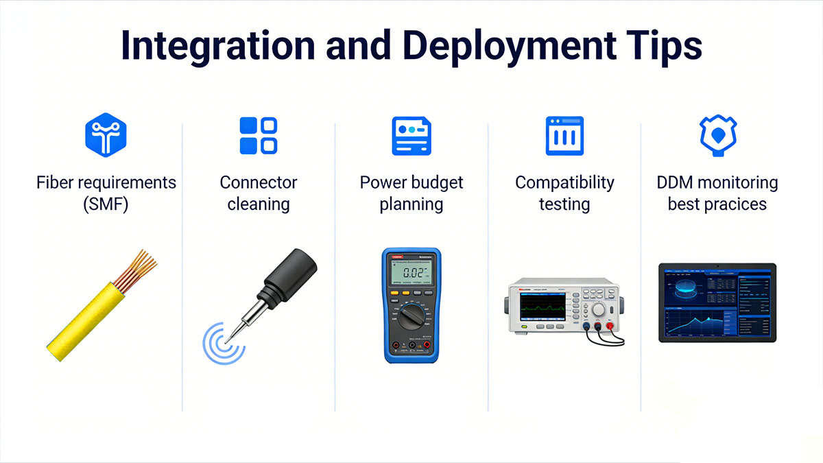
The following guidelines help ensure reliable integration of 40GBASE-ER4 modules into production networks.
Plan the Optical Budget Before Deployment
Long-reach 40GBASE-ER4 links require careful optical budget validation to ensure sufficient margin across the full fiber span.
| Factor | Check Before Deployment | Why It Matters |
|---|---|---|
| Fiber distance | ≤40km | Within spec reach |
| Total link loss | Within budget | Avoid Rx sensitivity limit |
| Connector loss | Minimized | Prevent margin reduction |
| Splice loss | Verified | Maintain signal strength |
Recommended steps:
- Calculate total link attenuation
- Include connector and patch panel loss
- Verify Rx power margin
- Test with optical power meter
Long-distance links should always maintain safety margin between expected receive power and module sensitivity thresholds.
Use Proper Fiber and Connectivity
40GBASE-ER4 is designed exclusively for single-mode fiber with duplex LC connectors, and fiber quality directly affects link stability.
| Requirement | Recommendation | Impact |
|---|---|---|
| Fiber type | OS2 SMF | Long reach |
| Connector type | Duplex LC | Standard interface |
| Connector cleanliness | Clean before install | Prevent loss |
| Patch quality | Low insertion loss | Stable link |
Best practices:
- Clean connectors before insertion
- Use certified SMF jumpers
- Avoid tight bend radius
- Verify patch panel quality
Connector contamination is one of the most common causes of link failure in long-distance optical deployments.
Verify Compatibility with Host Equipment
Ensure that switches and routers support 40GBASE-ER4 QSFP+ module and can handle their power and thermal requirements.
| Check Item | Why It Matters |
|---|---|
| QSFP+ port support | Module recognition |
| Power budget per port | ER4 higher consumption |
| Cooling capacity | Thermal stability |
| Firmware compatibility | DDM access |
| Alarm handling | Monitoring integration |
Some platforms impose power limits per port group. Confirm that the system can support ER4 modules, especially in high-density configurations.
Manage Power and Thermal Conditions
40GBASE-ER4 modules typically consume more power than short-reach optics, making airflow and thermal management important in dense chassis.
Deployment considerations:
- Maintain front-to-back airflow
- Avoid blocking ventilation
- Monitor module temperature via DDM
- Distribute high-power optics across chassis
- Validate operation in full-port scenarios
Excessive heat can affect optical output stability and long-term reliability, particularly in high-density switching environments.
Use DDM for Commissioning and Monitoring
Digital Diagnostics Monitoring should be used during installation and ongoing operation to verify link health.
| Monitoring Step | Purpose |
|---|---|
| Check Tx power | Confirm output level |
| Check Rx power | Validate link margin |
| Monitor temperature | Prevent overheating |
| Watch alarms | Detect faults |
| Track trends | Predict degradation |
Recommended workflow:
- Install modules and fiber
- Check DDM readings
- Confirm Rx power within range
- Record baseline values
- Monitor periodically
Tracking optical power over time helps identify fiber degradation or connector contamination before link failure occurs.
Validate Link Stability After Installation
After deployment, verify that the link operates within stable parameters under real traffic conditions.
Checklist:
- Confirm link up status
- Verify error-free transmission
- Check DDM values
- Validate temperature stability
- Confirm no LOS alarms
For metro or campus links near the maximum reach, testing under load helps confirm that the optical budget is sufficient.
? FAQs About 40GBASE-ER4

Q1: What distance does 40GBASE-ER4 support?
Up to 40km over single-mode fiber with appropriate optical budget and link conditions.
Q2: What connector type does a 40GBASE-ER4 module use?
Duplex LC connectors for transmit and receive over single-mode fiber.
Q3: Is 40GBASE-ER4 compatible with standard QSFP+ ports?
Yes. It follows the QSFP+ form factor and electrical interface defined for 40GbE switches and routers.
Q4: Does 40GBASE-ER4 use CWDM or DWDM wavelengths?
It uses four CWDM wavelengths multiplexed internally to deliver 40Gbps over a single fiber pair.
Q5: Does 40GBASE-ER4 support Digital Diagnostics Monitoring (DDM)?
Yes. Most modules provide real-time monitoring for temperature, voltage, bias current, and optical power.
Q6: What fiber type is required for 40GBASE-ER4?
Standard single-mode fiber (typically G.652 compliant) is required for full-distance operation.
? Conclusion

40GBASE-ER4 remains the most practical 40GbE long-distance optical standard for up to 40km single-mode fiber links, providing stable CWDM-based transmission for metro DCI, campus backbones, and extended core networks.
By understanding its architecture, key specifications, interface design, and deployment considerations, network engineers can confidently integrate 40GBASE-ER4 modules into existing QSFP+ infrastructures while maintaining predictable optical budgets and long-term reliability. This makes it a structured and proven solution for organizations that need native 40GbE connectivity across geographically distributed sites without introducing unnecessary optical transport complexity.
For teams planning or maintaining long-reach 40GbE links, reviewing specification alignment, fiber conditions, and monitoring capabilities will help ensure consistent performance across real-world deployments. To explore compatible 40GBASE-ER4 module options and detailed technical references, visit the LINK-PP Official Store for further product documentation and solution guidance.







