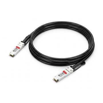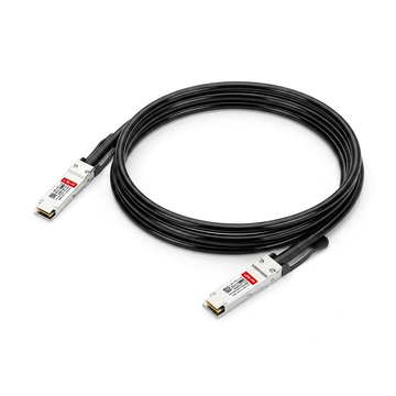


























In modern data centers, the demand for high-speed, reliable connectivity within server racks has never been greater. To meet this need efficiently, network engineers frequently turn to the QSFP-100G-CU1M, a Cisco Direct Attach Copper (DAC) cable designed for high-density environments. This passive twinax cable offers a seamless, plug-and-play solution for establishing blistering 100Gbps speeds without the complexity of optical hardware.
As data center architectures evolve, Top-of-Rack (ToR) deployment has emerged as the standard layout for minimizing cable clutter and maximizing performance. Within these standard 42U server racks, managing short-distance connections between servers and access switches requires a balance of speed, low latency, and cost-efficiency. By utilizing 1-meter copper DACs, operators can optimize their rack layout and budget while maintaining peak network throughput.
⏬ An Introduction to the QSFP-100G-CU1M Cisco DAC for ToR Networks
Implementing Top-of-Rack (ToR) architecture requires a deep understanding of the hardware that keeps data moving efficiently. The QSFP-100G-CU1M Cisco DAC serves as a foundational component in these setups, bridging the gap between high-density switches and servers. Exploring its core mechanics, technical specifications, and compatibility features reveals why it remains a good choice for modern data center managers.
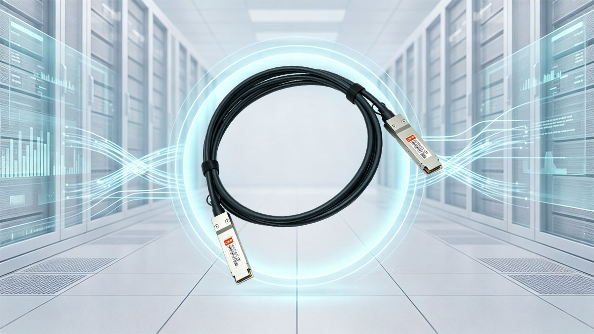
Core Definition and Operational Mechanism of the 100G Passive Twinax
The QSFP-100G-CU1M is a passive Direct Attach Copper (DAC) twinax cable designed for short-range, high-bandwidth communication. Unlike active cables that require internal components to boost signals, this passive cable transmits data directly over copper wiring without drawing extra power. It utilizes four differential lanes, each capable of transmitting data at speeds up to 25Gbps using NRZ signaling technologies.
By eliminating the need for optical-to-electrical conversion, the QSFP-100G-CU1M operates with near-zero latency and minimal heat generation. The twinax design features shielded copper pairs that protect the high-frequency signals from electromagnetic interference (EMI). This simple yet highly effective mechanism ensures robust, uninterrupted data flow between adjacent hardware devices in a single rack enclosure.
Key Technical Specifications: Form Factor, Data Rate, and 1-Meter Range Constraints
Built on the industry-standard QSFP28 interface, the QSFP-100G-CU1M delivers a massive 100Gbps aggregate data rate. This form factor is engineered for high port density, allowing network administrators to maximize the utility of their limited ToR switch space. It supports hot-swappable installation, meaning it can be plugged into an active system without causing network downtime.
However, the physical properties of high-speed copper transmission impose a strict 1-meter range constraint on the QSFP-100G-CU1M Cisco cable. Beyond this 1-meter limit, signal attenuation and degradation can compromise data integrity and cause packet loss. Therefore, this specific length is precision-engineered exclusively for adjacent or intra-rack connections where switches and servers sit in close proximity.
Decoding the Cisco Compatibility Layer and Its Significance in ToR Environments
Cisco switches utilize a proprietary EEPROM compatibility layer to verify authorized hardware and optimize signal performance settings automatically. The QSFP-100G-CU1M Cisco DAC contains programmed firmware that communicates directly with the switch's operating system, such as Cisco NX-OS. This seamless integration ensures the port recognizes the cable instantly, eliminating the risk of frustrating "unsupported transceiver" error codes during deployment.
In high-stakes ToR environments, this compatibility guarantees that error-correction algorithms and diagnostic monitoring work flawlessly out of the box. Network administrators can easily pull real-time data and status updates directly through the standard Cisco command-line interface. Ultimately, utilizing fully compatible QSFP-100G-CU1M cables reduces troubleshooting times and streamlines large-scale infrastructure rollouts.
Fundamental Differences Between QSFP-100G-CU1M Copper and Optical Transceivers
While both copper DACs and optical transceivers deliver incredible 100G speeds, they rely on entirely different physical mediums and engineering principles to transmit data. To better understand how the QSFP-100G-CU1M stacks up against optical alternatives, it is helpful to look at their core design differences.
The following table provides a clear comparison of their operational features and best-use scenarios within the data center:
| Feature / Specification | QSFP-100G-CU1M Copper DAC |
100G Optical Transceiver (e.g., 100GBASE-SR4) |
| Transmission Medium | Copper Twinaxial Cable | Fiber Optic Cable |
| Maximum Distance | 1m | Up to 100m |
| Power Consumption | Virtually Zero | ~2.5W to 3.0W per Module |
| Latency | Ultra-low (No signal conversion) | Low (Requires Electrical-optical Conversion) |
| Average Cost | Economical and Budget-friendly | Premium (Requires Separate Modules and Fiber Patches) |
| Primary Application | Intra-rack Server-to-switch Links | Inter-rack Switch-to-switch and High-density Cluster Connections |
Choosing the right option depends heavily on the physical layout and distance requirements of your network. For short-range, single-rack setups, the QSFP-100G-CU1M DAC cable provides an unmatched combination of low latency, simplicity, and cost savings over fiber optics.
⏬ Why QSFP-100G-CU1M Is the Ideal Choice for Top-of-Rack Architecture
Top-of-Rack (ToR) deployments demand specialized hardware that can keep pace with rapid data transmission and compact space requirements. The QSFP-100G-CU1M DAC cable stands out as a highly specialized solution engineered to optimize these specific localized environments. Understanding its operational advantages reveals why this copper alternative is an essential component for efficient rack management.
Meeting the Short-Distance Demands of Intra-Rack Server Connections
Top-of-Rack architectures inherently feature a localized layout where servers sit directly beneath the access switch. Because the physical distance between the ToR switch and the server network interface cards (NICs) is highly compressed, long-range cabling is entirely unnecessary. The 1-meter length of the QSFP-100G-CU1M provides just enough reach to connect these adjacent devices without creating dangerous pools of slack.
Excessive cable slack can quickly choke a server cabinet, restricting airflow and complicating routine maintenance. Deploying the QSFP-100G-CU1M ensures clean, precise point-to-point connections within the restricted confines of a single rack. This tailored distance matches the physical reality of ToR layouts, keeping infrastructure tidy and organized.
Eliminating Optical Transceiver Costs in High-Density ToR Deployments
Populating a high-density 100G ToR switch with traditional optical transceivers can quickly drain an enterprise IT budget. Optical setups require purchasing two separate optical modules alongside specialized fiber patch cables for every single link. Choosing the QSFP-100G-CU1M dramatically reduces capital expenditure by combining the connectors and the cable into a single, factory-terminated unit.
When scaling up to support dozens of servers across multiple data center racks, these financial savings multiply rapidly. The budget-friendly nature of the QSFP-100G-CU1M solution allows organizations to allocate financial resources to other critical hardware upgrades. Ultimately, copper DACs offer an incredibly economical pathway to achieving massive 100G throughput at the access layer.
Ultra-Low Latency: The Crucial Factor for ToR Compute Clusters
Modern high-performance compute clusters and financial trading systems depend heavily on microseconds of computational speed. Optical transceivers introduce minute delays because they must convert electrical signals into light pulses and then back again. The QSFP-100G-CU1M bypasses this translation layer completely by keeping the data entirely in its native electrical format.
This direct, raw electrical path results in ultra-low latency that maximizes the performance of interconnected server clusters. For data-intensive applications running across a ToR network, the QSFP-100G-CU1M provides the near-instantaneous response times needed for real-time processing. Minimizing latency at the rack level directly improves the efficiency of the entire distributed application stack.
Power Efficiency: Zero-Power Consumption of Passive Copper in Racks
Energy consumption and heat dissipation are two of the biggest operational challenges facing modern data center managers. Active optical modules generate measurable heat and can draw several watts of electricity per port to power their internal lasers. In contrast, the passive architecture of the QSFP-100G-CU1M demands zero power from the switch to transmit data over its copper medium.
By deploying the QSFP-100G-CU1M DAC across dozens of ToR switch ports, facilities can noticeably lower their overall power profile. Reduced power consumption at the port level also translates to less ambient heat generated inside the tight enclosure of the server rack. This lower thermal output eases the burden on data center cooling systems, paving the way for more sustainable operations.
⏬ Physical Rack Layout Design with QSFP-100G-CU1M in a ToR Environment
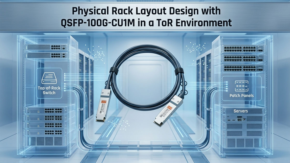
Designing the physical layout of a server cabinet requires careful spatial planning to ensure all hardware links remain within operational limits. The QSFP-100G-CU1M copper DAC imposes strict physical boundaries that directly influence how switches and servers are arranged. Properly managing these physical constraints guarantees structural organization and protects critical high-speed data pathways.
Mapping the 1-Meter Reach Across a Standard 42U Server Rack
A standard 42U server rack stands over six feet tall, which means vertical distance can quickly exhaust a short cable. Because the QSFP-100G-CU1M has a strict 1-meter length limit, network installers must map out the exact reach boundaries before mounting hardware. Miscalculating this distance can lead to overstretched lines or ports that simply cannot be plugged in.
Key considerations for mapping this specific 1-meter boundary include the following points:
- Upper RU Limits: Reaches up to 10 to 12 rack units downward from a top-mounted switch.
- Lower RU Inaccessibility: Bottom-mounted servers will remain completely out of reach.
- Straight-Line Routing: Demands direct vertical paths to maximize the usable length.
- Patch Panel Exclusion: Cannot bypass intermediate patching hardware due to length limits.
Strategic Switch Placement: Top-of-Rack vs. Middle-of-Rack Accessibility
The position of the access switch determines how many servers can successfully utilize short copper connections. While a traditional Top-of-Rack placement is excellent for upper-tier equipment, it leaves the lowest servers stranded without connectivity. Moving the switch to a Middle-of-Rack (MoR) position can sometimes maximize the efficiency of the QSFP-100G-CU1M Cisco cable layout.
Evaluating the placement of the switch directly impacts cable accessibility across the cabinet:
- Top-of-Rack Setup: Perfect for clusters occupying the top half of the cabinet.
- Middle-of-Rack Alternative: Doubles the number of reachable servers by expanding reach upward and downward.
- Density Optimization: Ensures all 1-meter QSFP-100G-CU1M lines are fully utilized.
- Symmetry Benefits: Creates balanced, equal-length cable bundles on both sides of the switch.
Managing Cable Bend Radius and Strain Relief within Tight Enclosures
Thick twinaxial copper cables are heavy and inherently rigid compared to flexible fiber optic patches. If the QSFP-100G-CU1M is bent too sharply near the connector boot, internal copper pairs can warp and degrade signal performance. Implementing proper strain relief ensures that the heavy weight of the copper does not pull downward on the delicate switch ports.
Maintaining structural integrity within tight rack enclosures requires adhering to specific handling rules:
- Minimum Bend Radius: Keep bends at least five times the diameter of the cable.
- Connector Boot Protection: Avoid any sharp twisting immediately behind the port connection.
- Support Bars: Use horizontal lacing bars to support the heavy weight of copper bundles.
- Velcro Ties: Secure lines loosely to allow natural flexing without pinching the shielding.
Cable Grooming and Airflow Optimization to Prevent Rack Hotspots
High-density server configurations generate massive amounts of heat that must be exhausted through the back of the rack. Thick bundles of QSFP-100G-CU1M Cisco cables can act like a solid wall, blocking exhaust fans and creating dangerous heat pockets. Proper cable grooming routes these thick copper lines along the sides of the cabinet frame to keep the exhaust path clear.
Optimizing the airflow around copper bundles involves several essential cable management practices:
- Side-Channel Routing: Push heavy copper bundles into the vertical side channels of the rack.
- Exhaust Path Clearance: Keep the immediate area behind server fans completely unobstructed.
- Bundle Size Limitations: Group cables in small, separate bundles rather than one massive cluster.
- Airflow Monitoring: Check that the passive QSFP-100G-CU1M lines are not absorbing trapped heat.
⏬ Network Topology: Integrating QSFP-100G-CU1M in ToR Leaf-Spine Designs
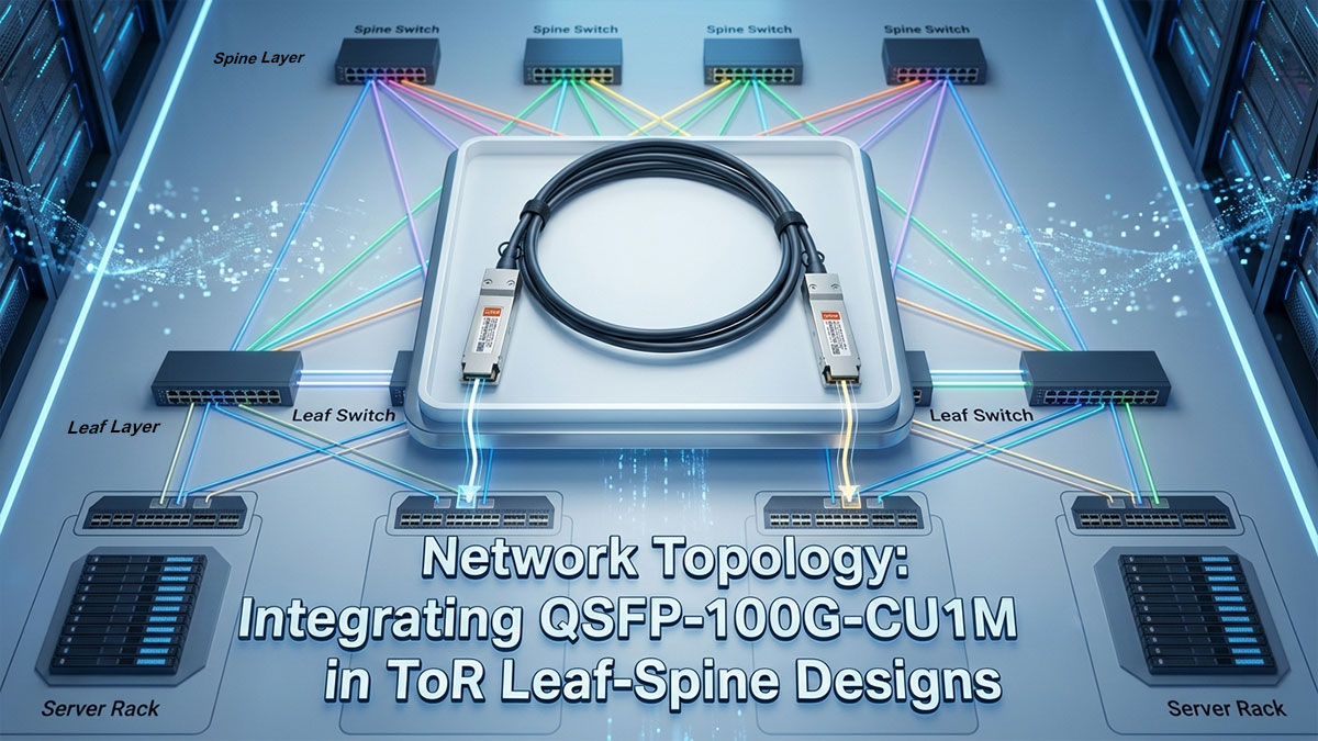
Modern data center architectures rely heavily on leaf-spine topologies to ensure predictable, non-blocking traffic flows. Within this framework, the QSFP-100G-CU1M Cisco DAC plays a pivotal role at the edge of the fabric, connecting individual computing nodes to the network. Integrating these high-speed copper links correctly ensures optimal bandwidth distribution and hardware utilization throughout the entire rack ecosystem.
Connecting High-Performance Downlink Servers to the ToR Leaf Switch
In a leaf-spine architecture, the Top-of-Rack switch functions as the "leaf," acting as the local access point for all computing hardware. The QSFP-100G-CU1M serves as the critical downlink connection, tying high-performance servers directly into this network fabric. Because these downlinks handle massive amounts of raw data, the 100Gbps capacity prevents localized bottlenecks at the server interface.
Using these passive copper lines for downlinks creates a highly stable localized network layer. The direct-attach design of the QSFP-100G-CU1M cable ensures that data moving from the server reaches the leaf switch instantly without transit hiccups. This solid foundation at the downlink level is essential for supporting resource-heavy enterprise software and virtualization platforms.
Optimizing Port Density and Throughput on ToR Access Layers
Maximizing the efficiency of a ToR access layer requires balancing physical port availability with total throughput potential. The compact form factor of the QSFP-100G-CU1M allows switches to accommodate dozens of high-speed interfaces across a single rack unit. This dense concentration of ports enables data centers to aggregate massive amounts of bandwidth without expanding their physical footprint.
By deploying the QSFP-100G-CU1M across all available downlink ports, network architects can maximize the total data throughput of the access switch. This configuration eliminates the need for lower-speed breakout cables, keeping the topology uniform and much easier to manage. Ultimately, high port density combined with consistent 100G speeds leads to a highly optimized edge layer.
Designing Dual-Homed Server Configurations for Fault-Tolerant ToR Links
To prevent a single point of failure from taking down critical enterprise applications, modern servers utilize dual-homed configurations. In this setup, two separate QSFP-100G-CU1M cables run from a single server to two independent leaf switches within the rack. If one switch fails or undergoes routine maintenance, traffic automatically reroutes through the secondary copper link.
This redundant design leverages technologies like Link Aggregation Control Protocol (LACP) or Virtual PortChannel (vPC) to combine both paths. Utilizing identical QSFP-100G-CU1M Cisco cables for both sides of the dual-homed link ensures symmetric performance and equal latency characteristics. This consistency makes it much easier for the operating system to load-balance traffic dynamically across both active paths.
Handling Oversubscription and Bandwidth Allocation at the Rack Level
Oversubscription occurs when the total potential bandwidth of all server downlinks exceeds the capacity of the uplinks leading to the spine switches. Since dozens of QSFP-100G-CU1M downlinks can quickly flood a ToR leaf switch, managing this ratio is vital for maintaining network performance. Network engineers must carefully calculate the aggregate rack traffic to ensure the uplinks are not overwhelmed during peak loads.
When deploying multiple QSFP-100G-CU1M lines, configuring proper Quality of Service (QoS) and traffic shaping policies helps maintain balance. High-priority data packets receive guaranteed passage, preventing less critical traffic from consuming all the copper link capacity. Strategic bandwidth allocation ensures that the 100Gbps speeds provided by each cable are used effectively without choking the upstream fabric.
⏬ Installation and Hardware Deployment of QSFP-100G-CU1M in ToR Switches
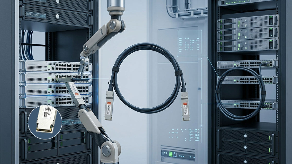
Proper physical deployment is essential to guarantee the long-term reliability of high-speed data center links. Installing the QSFP-100G-CU1M DAC requires a combination of careful hardware handling and strategic cable organization. Adhering to standardized installation procedures ensures optimal signal performance and prevents damage to expensive switch ports.
Pre-Deployment Inspection of Copper Twinax Connectors
Before inserting any hardware into a production switch, a thorough physical inspection must be performed on the cable assembly. Minor manufacturing defects or shipping damage to the QSFP-100G-CU1M connector pins can permanently ruin a switch port. Catching these issues early saves time and protects the data center infrastructure from unnecessary hardware failures.
The pre-deployment checklist focuses on verifying the physical integrity of the cable ends:
- Inspect gold pins: Check for scratches, corrosion, or bent contacts inside the transceiver head.
- Examine the casing: Look for dents or cracks on the metal pull-tab housing.
- Verify cable jacket: Search for deep cuts or kinks along the copper insulation.
- Test the pull-tab: Ensure the release latch springs back into position smoothly.
Correct Hot-Plugging Procedures for Cisco ToR Hardware Ports
Cisco Top-of-Rack switches fully support hot-swapping, allowing administrators to add connections without powering down the system. However, forcing the QSFP-100G-CU1M into a slot at a bad angle can misalign the internal interface pins. Following a disciplined insertion methodology guarantees a secure connection and triggers immediate software recognition.
Adhering to these sequential steps ensures a flawless hot-plugging experience:
- Align the module: Face the release pull-tab in the correct orientation for the port row.
- Insert smoothly: Slide the transceiver into the slot using gentle, even pressure.
- Listen for the click: Push until the mechanical latch engages firmly inside the switch.
- Verify the LED: Check that the port indicator light turns green.
Securing and Labeling DAC Lines for Clear Infrastructure Management
High-density server racks can quickly descend into chaos without a strict identification system for cabling. Because multiple QSFP-100G-CU1M Cisco cables look identical, labeling both ends of every line is critical for efficient maintenance. Securely fastening the lines also prevents accidental disconnects when engineers work inside the back of the cabinet.
Implementing a clear labeling and securing routine involves several straightforward steps:
- Apply dual labels: Mark the exact switch port and server ID on both cable ends.
- Use color-coded wraps: Differentiate production, management, or storage links visually.
- Anchor near the port: Fasten the cable to the rack frame close to the switch.
- Avoid tight cinching: Leave zip ties loose enough to slide along the jacket easily.
Utilizing Vertical Cable Managers for Multi-Server ToR Trunking
Managing the heavyweight of dozens of twinaxial copper lines requires robust structural support within the server enclosure. Vertical cable managers run alongside the rack frame, acting as a dedicated highway for the QSFP-100G-CU1M bundles. This setup routes the bulk of the weight away from the hardware interfaces, ensuring clean lines and open airflow pathways.
Organizing large cable bundles through vertical managers relies on these key practices:
- Route through fingers: Thread individual lines through the plastic management fingers carefully.
- Separate by direction: Group cables going to the left side of the switch away from the right.
- Maintain vertical drop: Let the heavy copper weight hang straight down naturally.
- Close the cover: Secure the manager door to protect the cables from external snags.
⏬ Troubleshooting QSFP-100G-CU1M Link and Performance Issues in ToR Racks
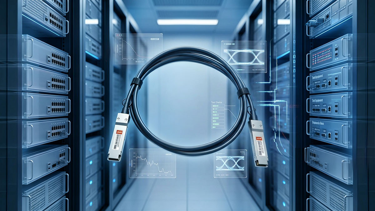
Maintaining an active high-speed network fabric requires a methodical approach to identifying and resolving hardware anomalies. Even highly reliable components like the QSFP-100G-CU1M Cisco DAC can occasionally encounter physical or configuration challenges within dense computing environments. Mastering standard diagnostic protocols allows network teams to minimize downtime and isolate problems quickly at the rack level.
Diagnosing "Link Down" and Port Flapping on ToR Switch Connections
A sudden "Link Down" status or rapid port flapping indicates a major breakdown in communication between the switch and the server. When deploying the QSFP-100G-CU1M, these unstable behaviors are frequently caused by an incomplete physical insertion or accumulated dust inside the slot. Administrators should first check the switch logs to observe how often the interface is resetting and look for hardware alerts.
If the port continues to flap, reseating the cable on both ends is the most logical first step in hardware diagnostics. Inspecting the physical connection ensures that the integrated locking mechanism on the QSFP-100G-CU1M has completely latched into place. If the issue persists across multiple ports, it may be necessary to test the interface with a known working spare line.
Fixing Autonegotiation and Speed Mismatches Between ToR Switch and NIC
Link stability issues often arise when the Top-of-Rack switch port and the server network interface card (NIC) disagree on operational parameters. While the QSFP-100G-CU1M is optimized for 100Gbps performance, mismatched port speed configurations can prevent the link from establishing entirely. This communication breakdown occurs when one side is locked to a specific speed while the other relies on automatic discovery protocols.
To resolve these speed mismatches, network engineers should manually lock both the switch port and the server NIC to 100G speeds. Bypassing standard autonegotiation rules ensures that both hardware interfaces apply the exact same timing and signaling configurations immediately. Standardizing these configuration variables across the QSFP-100G-CU1M Cisco link quickly restores uniform communication across the access layer.
Identifying Bit Error Rates (BER) Caused by Copper Signal Degradation
High Bit Error Rates (BER) manifest as slow data transfers, intermittent packet drops, and corrupted file streams across the rack network. Because the QSFP-100G-CU1M transmits raw high-frequency electrical signals, physical degradation of the internal twinaxial wiring can corrupt moving data. This signal degradation is typically the result of structural abuse, such as exceeding the cable's maximum bend limit.
Data center managers can isolate these performance drops by running built-in digital diagnostic commands via the network operating system. Monitoring the error counters over a set timeframe reveals whether the copper shielding has been compromised by external interference or pinching. Replacing an over-bent QSFP-100G-CU1M line is usually the fastest remedy for cleaning up signal integrity and restoring baseline throughput.
Differentiating Between Cable Damage and Cisco OS Configuration Errors
When a 100G link fails to activate, determining whether the fault lies with the physical hardware or the software configuration is crucial. A physically broken QSFP-100G-CU1M Cisco cable will exhibit the same inactive status as a port that has been accidentally disabled via software. Running a systematic cross-check prevents teams from wasting time replacing functional copper hardware.
Administrators should check the active command-line interface to ensure the port has not been put into an administrative "shutdown" state. Additionally, checking for error-disabled states caused by security violations or bad port mirroring profiles can rule out operating system overrides. If the switch configuration files are perfectly correct, the focus can confidently shift toward replacing the physical QSFP-100G-CU1M assembly.
⏬ Conclusion: Driving ToR Network Success with QSFP-100G-CU1M DACs

Deploying the QSFP-100G-CU1M Direct Attach Copper cable is a highly effective strategy for optimizing short-range Top-of-Rack data center infrastructure. By providing a perfect balance of 100Gbps high-speed performance, ultra-low latency, and zero-power consumption, this passive twinax solution answers the core operational challenges of modern server racks. When combined with proper physical layout planning and disciplined installation practices, it ensures a reliable, cost-efficient edge layer that supports heavy computational workloads seamlessly.
While short-distance intra-rack connections are best served by economical copper hardware, expanding your network fabric over longer distances demands high-performance optical equipment. For enterprise-grade projects requiring premium fiber connectivity and reliable long-range optical transceivers, check out the specialized options available at the LINK-PP Official Store to complete your high-density network architecture. Investing in the right combination of copper DACs and robust optical modules guarantees long-term scaling success and maximum network uptime for your entire infrastructure.