


































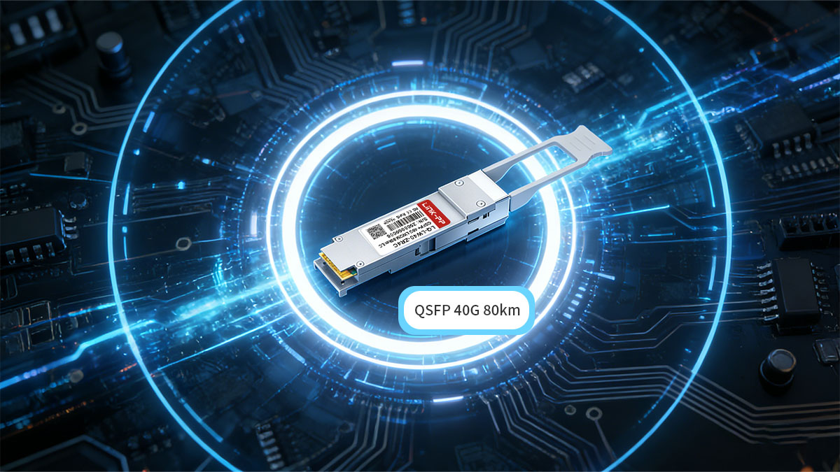
QSFP 40G 80km transceivers are designed for long-distance 40Gbps links where standard LR4 (10km) or ER4 (40km) optics cannot meet reach requirements. They are typically deployed in metro networks, inter-campus backbones, and data center interconnect (DCI) scenarios that require up to 80km transmission over single-mode fiber without migrating to higher-cost coherent 100G platforms.
As 100G and 400G networks expand, 40G long-reach optics still play a practical role in regional infrastructure, especially where existing 40G switching platforms remain in service. A QSFP 40G 80km module allows operators to extend link distance significantly while maintaining the QSFP+ form factor, simplifying deployment and preserving compatibility with many 40G switches and routers.
This guide explains what QSFP 40G 80km modules are, how they work, their key specifications, and when they are the right choice for long-distance optical networking. It also covers fiber requirements, interoperability considerations, and how these modules compare with other 40G long-reach options to help engineers and buyers make informed deployment decisions.
? What Is a QSFP 40G 80km Transceiver?
A QSFP 40G 80km transceiver is a long-reach 40Gbps optical module designed to transmit data up to 80km over single-mode fiber, typically based on extended-reach 40G ZR4 or enhanced ER4 optical architectures. It uses the QSFP+ form factor and duplex LC interface, allowing 40G network devices to connect across metro-scale or inter-city distances without deploying full DWDM coherent systems.
These modules are primarily used where 10km (LR4) and 40km (ER4) optics are insufficient but upgrading to 100G coherent transport is not yet necessary or cost-effective. In practical deployments, QSFP 40G 80km optics are often found in data center interconnect (DCI), metro aggregation, and long-distance enterprise backbone links.
How QSFP 40G 80km Transmission Works
QSFP 40G 80km modules extend reach by using four LAN-WDM wavelengths, higher optical launch power, and improved receiver sensitivity compared with standard 40G LR4/ER4 modules. This allows them to overcome fiber attenuation and dispersion over longer spans.
Key technical characteristics:
-
4 × 10Gbps optical lanes multiplexed into 40Gbps
-
Operates over duplex single-mode fiber (OS2)
-
Typically requires a higher optical link budget
-
May rely on FEC support in host equipment
-
In some deployments, can work with optical amplification
Unlike coherent long-haul systems, these modules remain direct-detect optics, which keeps power consumption and system complexity lower than DWDM transport platforms while still enabling metro-scale distances.
QSFP 40G 80km vs Standard 40G Optics
The main difference between a QSFP 40G 80km module and standard 40G optics is its significantly larger optical budget and extended reach.
| Module Type | Typical Reach | Primary Use |
|---|---|---|
| QSFP 40G LR4 | 10km | Campus or short metro |
| QSFP 40G ER4 | 40km | Regional backbone |
| QSFP 40G 80km | Up to 80km | Metro/DCI long reach |
Because of the higher transmit power and sensitivity required, 80km modules generally have higher power consumption and stricter link design requirements than LR4 or ER4 optics.
When an 80km 40G Module Is Used
A QSFP 40G 80km transceiver is used when a network must maintain 40Gbps infrastructure while extending link distance beyond 40km without migrating to coherent 100G transport.
Common decision triggers:
-
Two data centers located 50–80km apart
-
Metro aggregation links across a region
-
Enterprise backbone between cities
-
Gradual migration from 40G to 100G
-
Cost constraints preventing coherent optics
In these scenarios, QSFP 40G 80km modules provide a balance between reach, cost, and deployment simplicity while remaining compatible with many existing 40G switching platforms.
? Key Specifications of QSFP 40G 80km Modules
QSFP 40G 80km modules are defined by a higher optical link budget, stronger transmit power, and improved receiver sensitivity compared with LR4 or ER4 optics, enabling stable 40Gbps transmission over long-distance single-mode fiber. Understanding these specifications is critical for link planning, compatibility checks, and deployment feasibility in metro or inter-city networks.
Optical and Electrical Specifications
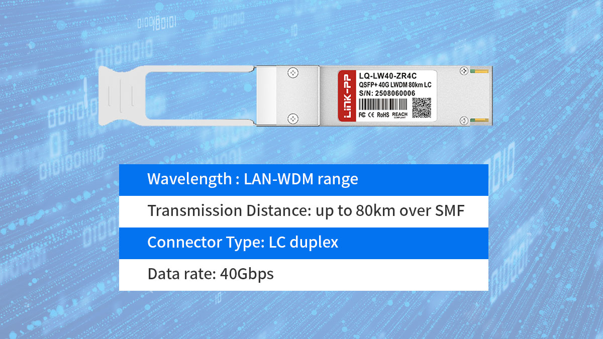
A typical QSFP 40G 80km module uses four wavelengths and operates over duplex single-mode fiber with an extended optical budget suitable for long spans.
| Parameter | Typical Value | Notes |
|---|---|---|
| Form factor | QSFP+ | 40G switch/router compatible |
| Data rate | 40Gbps | 4×10Gbps lanes |
| Wavelength | LAN-WDM | 4 optical channels |
| Connector | LC duplex | Single-mode fiber required |
| Reach | Up to 80km | Depends on link budget |
These modules multiplex four optical lanes internally and transmit over a duplex LC interface, making them physically similar to LR4 and ER4 optics but with significantly stronger optical performance.
Because of the longer reach, actual achievable distance depends on fiber attenuation, splice loss, and patch panel quality rather than module specs alone.
Power Consumption and Environmental Specs
QSFP 40G 80km modules typically consume more power than LR4 or ER4 optics due to higher transmit output and receiver sensitivity requirements.
| Parameter | Typical Range | Notes |
|---|---|---|
| Power consumption | 3.5–5.5W | Higher than LR4 |
| Operating temp | 0–70°C or industrial | Depends on model |
| DOM/DDM | Supported | Real-time monitoring |
| Voltage | Standard QSFP+ | Host compliant |
Higher power draw means:
-
Switch thermal capacity must be checked
-
Dense deployments may require airflow planning
-
Some legacy switches may not support high-power optics
Digital diagnostics monitoring (DOM/DDM) is essential in long-distance deployments because it allows engineers to track optical power levels and detect link degradation early.
Optical Budget and Link Engineering
The defining specification of a QSFP 40G 80km module is its optical link budget, which determines whether a real-world fiber span can support stable transmission.
| Factor | Typical Range | Impact |
|---|---|---|
| TX output power | High | Enables long reach |
| Receiver sensitivity | Enhanced | Supports weak signals |
| Optical budget | ~23–30dB | Core 80km capability |
| FEC support | Often required | Improves margin |
The total link budget must account for:
-
Fiber attenuation (~0.25dB/km typical)
-
Connector loss
-
Splice loss
-
Patch panels
-
Aging margin
For many 80km deployments, forward error correction (FEC) on the host side improves stability and increases allowable link loss. In some cases, especially near the upper distance limit, optical amplification (such as EDFA) may be used to maintain signal quality.
Why Specifications Matter for Deployment
QSFP 40G 80km specifications directly determine whether a link can operate reliably without additional optical equipment.
Before deployment, engineers must verify:
-
Total fiber distance
-
Estimated link loss
-
Switch compatibility with high-power QSFP optics
-
Temperature environment
-
Whether amplification is needed
Ignoring these factors can result in unstable links even if the nominal distance appears within 80km. Proper interpretation of module specifications ensures that the optical path, hardware platform, and network design all align for long-distance 40G transmission.
? Fiber and Cabling Requirements
QSFP 40G 80km links require low-loss single-mode fiber, clean connector paths, and careful link budget planning to achieve stable transmission over long distances. Even when the module is rated for 80km, real-world performance depends heavily on fiber attenuation, splice quality, and connector loss across the entire optical path.
In most deployments, OS2 single-mode fiber with properly managed patch panels and minimal insertion loss is mandatory. Poor cabling practices can reduce achievable distance well below the rated reach.
Fiber Type and Distance Support
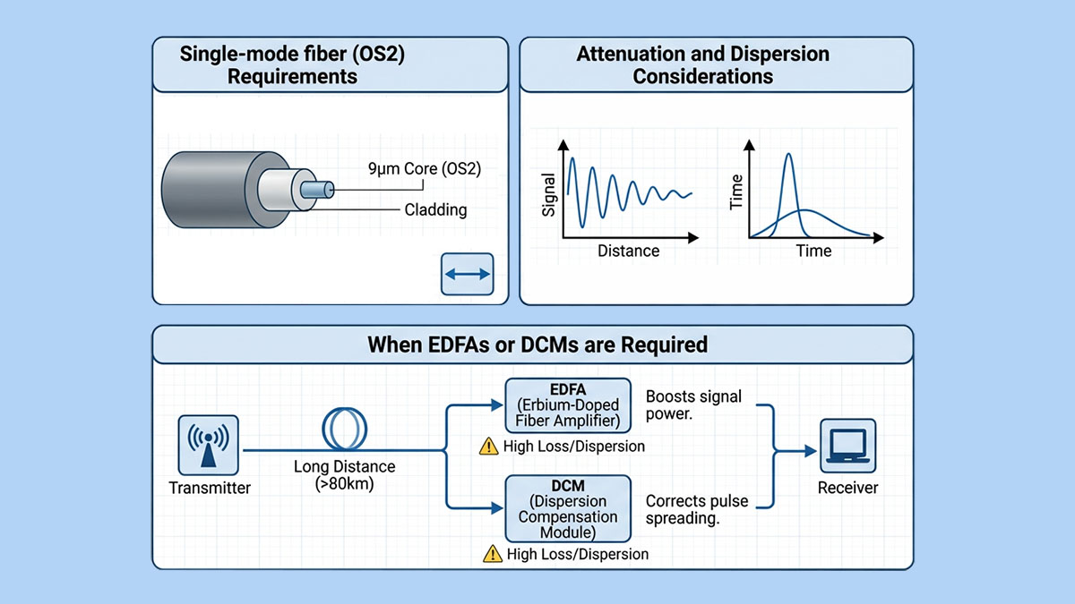
QSFP 40G 80km modules are designed specifically for single-mode fiber (SMF), typically OS2, which provides the low attenuation required for metro-scale transmission.
| Fiber Type | Supported Distance | Suitability |
|---|---|---|
| OS2 SMF | Up to 80km | Recommended |
| OS1 SMF | Limited | Higher attenuation |
| Multimode (OM3/OM4) | Not supported | Incompatible |
OS2 fiber typically has attenuation around 0.22–0.25dB/km, which is essential for long-distance links. Using older or higher-loss fiber can significantly reduce achievable reach and may require optical amplification to compensate.
Connector and Patch Panel Considerations
Connector loss and patch panel quality can determine whether an 80km link succeeds or fails, even when fiber distance is within specification.
Key practices:
-
Use LC duplex connectors with low insertion loss
-
Minimize patch panel hops where possible
-
Ensure connectors are properly cleaned
-
Avoid excessive adapters
-
Document all connection points
Every connector pair typically introduces 0.3–0.5dB loss. Over long distances, these small losses accumulate and directly reduce the available optical margin.
For example:
-
80km fiber span
-
Multiple patch panels
-
Several splice points
The combined loss can approach or exceed the module’s optical budget if not carefully controlled.
Link Budget Planning
An 80km optical link must be engineered using total link loss calculations rather than relying only on nominal module distance ratings.
Typical link loss components:
-
Fiber attenuation per kilometer
-
Splice loss
-
Connector loss
-
Aging margin
-
Safety margin
Engineers should calculate total expected loss and compare it with the module’s optical budget. If the margin is too small, the link may experience instability, especially under temperature variation or fiber aging.
Checklist before deployment:
-
Measure actual fiber length
-
Estimate total attenuation
-
Confirm module optical budget
-
Verify switch FEC support
-
Allow margin for future degradation
When Optical Amplification May Be Needed
Some QSFP 40G 80km deployments—especially near the maximum distance or with higher-loss fiber—may require optical amplification to maintain signal integrity.
Amplification may be considered when:
-
Fiber distance approaches 80km
-
Multiple patch panels are present
-
Fiber quality is unknown
-
Link margin is below safe thresholds
Common approaches include:
-
EDFA placement at mid-span
-
Dispersion compensation where required
-
Optical power monitoring via DOM
However, many modern 80km modules are designed to operate without amplification if fiber quality and link design are optimized.
Cabling Best Practices for Stable 80km Links
Long-distance 40G links succeed when fiber infrastructure is treated as part of the optical system, not just passive cabling.
Best practices:
-
Use certified OS2 fiber
-
Keep connector count low
-
Clean and test all connections
-
Validate link loss before activation
-
Monitor optical power after deployment
Following these guidelines ensures that a QSFP 40G 80km module can operate reliably at full distance while maintaining sufficient optical margin for long-term network stability.
? Typical Applications of QSFP 40G 80km
QSFP 40G 80km optics are used where 40Gbps links must span metro or inter-city distances (40–80km) while keeping direct-detect architecture and QSFP+ switch compatibility. They are most effective in networks that already run 40G infrastructure and need extended reach without deploying coherent transport systems.
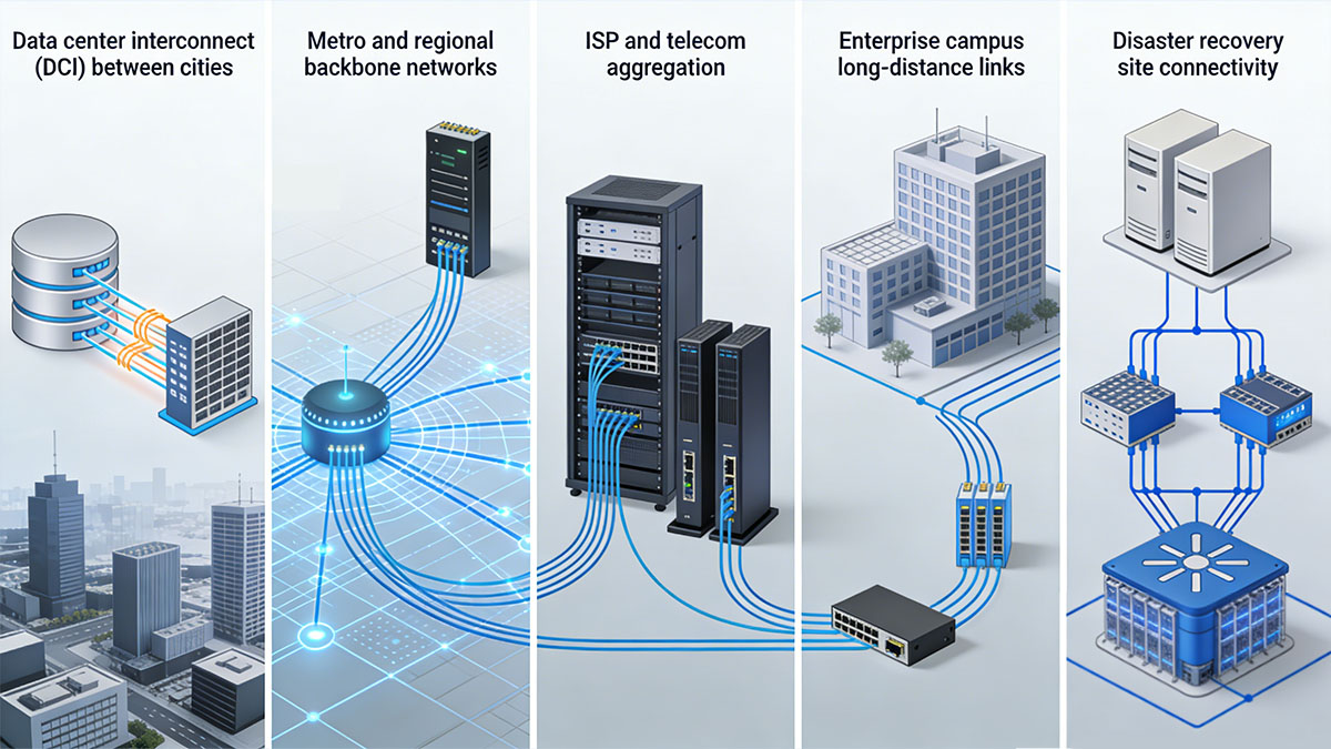
Below are the most common real-world deployment scenarios.
Data Center Interconnect (DCI) Between Cities
QSFP 40G 80km modules are widely used for inter-city data center interconnect when sites are within roughly 50–80km and dedicated dark fiber is available.
| DCI Type | Distance | Why 40G 80km |
|---|---|---|
| Active–active DC | 40–70km | Low latency, direct fiber |
| Primary–backup DC | 50–80km | Cost-controlled DR path |
| Edge–core DC | 30–80km | Avoids DWDM system |
In these DCI deployments, operators typically want to:
-
Reuse existing 40G switches
-
Maintain predictable latency
-
Avoid coherent optics cost
-
Deploy quickly over dark fiber
Because the modules operate over duplex SMF and LC connectors, they allow point-to-point DCI links without requiring a full optical transport platform.
Metro and Regional Backbone Networks
Metro backbone networks use QSFP 40G 80km optics to connect aggregation or core nodes across a city or region where fiber spans exceed ER4 capability.
Typical topology scenarios:
-
City ring backbone
-
Regional hub-to-hub links
-
Government network backbone
-
Utility infrastructure networks
Key decision factors:
-
Fiber routes often 50–80km
-
Multiple patch panels
-
Need for higher link margin
-
Existing 40G routing platforms
Because metro fiber paths often include splices and patch fields, the larger optical budget of 80km modules provides the margin needed for stable operation.
ISP and Telecom Aggregation
ISP and telecom operators deploy QSFP 40G 80km modules for aggregation links between access networks and regional core sites.
| Aggregation Scenario | Distance | Role |
|---|---|---|
| Access ring → core | 40–80km | Traffic uplink |
| Regional POP → core | 50–80km | Backbone feed |
| Mobile backhaul hub | 30–70km | Capacity aggregation |
These deployments often require:
-
Reliable long-distance transmission
-
Compatibility with routing platforms
-
Scalable 40G capacity
-
Cost efficiency vs coherent DWDM
In many telecom networks, 40G remains a practical aggregation layer, making 80km optics a suitable long-reach solution.
Enterprise Campus Long-Distance Links
Large enterprises use QSFP 40G 80km modules to connect campuses, production sites, or regional offices separated by tens of kilometers.
Typical environments:
-
Universities with distributed campuses
-
Financial institutions across cities
-
Manufacturing networks
-
Energy sector infrastructure
Common decision conditions:
-
Dedicated leased fiber
-
Existing 40G switches
-
Need for deterministic latency
-
Budget limits on transport systems
These modules allow enterprises to extend high-capacity backbone links without introducing additional optical transport equipment.
Disaster Recovery Site Connectivity
Disaster recovery (DR) networks often rely on QSFP 40G 80km links to connect primary and secondary data centers located in separate geographic zones.
| DR Scenario | Distance | Requirement |
|---|---|---|
| Primary ↔ DR site | 50–80km | Geographic separation |
| Backup replication | 40–70km | Stable throughput |
| Business continuity | Up to 80km | Dedicated fiber path |
In DR planning, the distance is typically long enough to ensure geographic redundancy but short enough to allow direct optical connections. QSFP 40G 80km modules provide:
-
Consistent latency
-
Dedicated bandwidth
-
Simplified architecture
-
Lower cost vs coherent transport
When These Applications Make Sense
QSFP 40G 80km is the right choice when a network must extend 40Gbps connectivity across metro or regional distances while maintaining simple, direct optical architecture.
Most suitable conditions:
-
Distance between 40km and 80km
-
Existing 40G switching platforms
-
Dedicated SMF available
-
Need to avoid DWDM systems
-
Controlled upgrade timeline to 100G
In these scenarios, the module serves as a practical long-reach extension of 40G infrastructure, enabling stable high-capacity connectivity across cities, campuses, and regional networks.
? QSFP 40G 80km vs Other 40G Long-Reach Modules
QSFP 40G 80km modules sit at the far end of the direct-detect 40G distance range, offering significantly longer reach than LR4 (10km) and ER4 (40km) optics but with higher power consumption, stricter link budgets, and more deployment planning requirements. Choosing between these options depends primarily on distance, fiber quality, and whether the network is transitioning toward coherent transport.
Understanding how 80km optics compare with other long-reach 40G modules helps determine when they are the most practical choice.
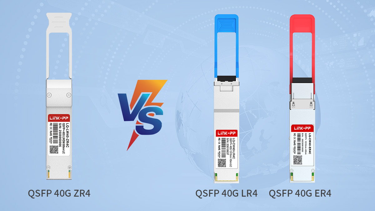
QSFP 40G 80km vs QSFP 40G LR4 (10km)
LR4 transceiver is designed for campus and short-metro links up to 10km, while 80km modules target inter-city or regional spans where LR4 cannot provide enough optical budget.
| Module Type | Reach | Typical Use |
|---|---|---|
| QSFP 40G LR4 | Up to 10km | Campus/DC links |
| QSFP 40G 80km | Up to 80km | Metro/DCI |
| Optical budget | Low–moderate | Very high |
LR4 modules are:
-
Lower power
-
Lower cost
-
Easier to deploy
-
Suitable for dense switch environments
QSFP 40G 80km modules are used only when distance requirements exceed LR4 capability. Deploying 80km optics on short links is generally unnecessary and may introduce excessive optical power that requires attenuation.
QSFP 40G 80km vs QSFP 40G ER4 (40km)
40GBASE-ER4 modules support up to 40km, making them the most common long-reach 40G option, while 80km optics extend beyond ER4 when metro distances exceed 40km.
| Module Type | Reach | Deployment Range |
|---|---|---|
| QSFP 40G ER4 | Up to 40km | Regional links |
| QSFP 40G 80km | Up to 80km | Inter-city links |
| Power consumption | Moderate | Higher |
Key differences:
-
80km modules have larger optical budgets
-
ER4 is easier to deploy
-
80km optics require tighter link planning
-
ER4 is more common in standard networks
Decision logic:
-
Use ER4 when distance ≤40km
-
Use 80km optics when distance exceeds ER4 capability
-
Consider link loss margin before choosing
Because many fiber paths include connectors and splices, a nominal 40km route may already approach ER4 limits. In those cases, 80km optics provide additional margin.
QSFP 40G 80km vs ZR4/Enhanced ZR Variants
Many 80km modules are based on extended ZR4-type designs, offering higher launch power and sensitivity compared with ER4 optics.
| Feature | ER4 | 80km/ZR4-type |
|---|---|---|
| Typical reach | 40km | 60–80km |
| Link budget | Moderate | High |
| Deployment complexity | Lower | Higher |
These extended-reach modules are often used in:
-
Metro DCI
-
Regional backbone
-
Telecom aggregation
However, they may:
-
Draw more power
-
Generate more heat
-
Require careful optical planning
QSFP 40G 80km vs Coherent 100G Long-Haul
When distances approach or exceed 80km, or when bandwidth scaling is required, coherent 100G solutions may become more cost-effective long term.
| Technology | Typical Reach | When Used |
|---|---|---|
| 40G 80km | Up to 80km | Extend 40G networks |
| 100G coherent | 80km+ | New builds/upgrade |
| DWDM transport | Long haul | Multi-channel systems |
Consider upgrading instead of using 40G 80km when:
-
Network is migrating to 100G
-
Capacity demand is increasing
-
DWDM system already exists
-
Distance exceeds 80km
But for many metro networks, 40G 80km remains practical because:
-
Existing 40G hardware is in place
-
Bandwidth per link is sufficient
-
Coherent systems are not justified
-
Simplicity is preferred
Selection Guidelines
Choose the module type based primarily on link distance, optical loss, and upgrade roadmap rather than only nominal reach.
Decision checklist:
-
≤10km → LR4
-
10–40km → ER4
-
40–80km → 80km optics
-
80km or scaling → coherent 100G
Also evaluate:
-
Available fiber quality
-
Power and thermal limits
-
Switch compatibility
-
Future network upgrades
Selecting the correct long-reach module ensures stable transmission while avoiding unnecessary cost or complexity.
? Compatibility and Interoperability Considerations
QSFP 40G 80km modules must be verified for switch compatibility, vendor coding, and optical interoperability before deployment, because long-reach optics operate closer to platform power, thermal, and signal tolerance limits than standard 40G transceiver. Even when a module meets optical specifications, incompatibility at the hardware or firmware level can prevent links from coming up or operating reliably.
Proper validation ensures stable long-distance operation across different vendors and network environments.
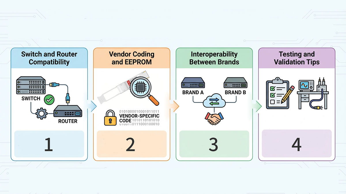
Switch and Router Compatibility
Not all 40G switches and routers support high-power long-reach QSFP modules, so platform compatibility must be confirmed before installation.
| Compatibility Factor | Why It Matters | What to Check |
|---|---|---|
| Power support | 80km optics draw more power | Port power budget |
| Thermal design | Higher heat output | Airflow capacity |
| Firmware support | Module recognition | Approved optics list |
| FEC capability | Improves stability | Platform support |
Before deployment:
-
Verify the switch supports extended-reach QSFP optics
-
Check vendor compatibility documentation
-
Confirm port power limits
-
Ensure firmware is up to date
-
Validate FEC support if required
Some legacy 40G switches were designed for LR4/SR4 optics only and may not support higher-power modules, even if the physical interface matches.
Vendor Coding and EEPROM
QSFP modules rely on EEPROM coding to identify vendor, type, and supported features, and many network platforms enforce vendor-specific compatibility checks.
| Coding Aspect | Impact |
|---|---|
| Vendor ID | Determines acceptance by switch |
| Part number | Must match platform profile |
| Checksum | Ensures module authenticity |
| DOM support | Enables monitoring |
If coding does not match the switch requirements:
-
Port may remain disabled
-
Module may show warnings
-
Monitoring may not function
-
Link stability may be affected
Solutions typically include:
-
Using vendor-compatible coded modules
-
Re-coding modules for specific platforms
-
Selecting multi-vendor compatible optics
Proper EEPROM coding ensures the host device recognizes the module as supported hardware.
Interoperability Between Brands
QSFP 40G 80km modules from different vendors can interoperate if optical parameters match, but long-distance links require tighter tolerance alignment than short-reach connections.
| Interoperability Factor | Requirement |
|---|---|
| Wavelength alignment | Must match channel plan |
| Optical budget | Within tolerance |
| Receiver sensitivity | Compatible levels |
| FEC usage | Same configuration |
When mixing vendors:
-
Ensure both ends use compatible 80km optics
-
Confirm optical power ranges overlap
-
Match FEC settings
-
Test for stable link margin
Because 80km links operate with lower margin than short links, small mismatches in transmit power or sensitivity can affect stability. Using the same module type at both ends is generally recommended.
Testing and Validation Tips
Long-distance 40G links should always be tested and validated before full production deployment, as real-world fiber conditions can differ from design assumptions.
Pre-deployment checks:
-
Measure actual fiber length
-
Test insertion loss
-
Verify connector quality
-
Confirm patch panel count
-
Calculate total link budget
Activation testing:
-
Check DOM optical power levels
-
Validate FEC status
-
Monitor error rates
-
Test under load
-
Observe thermal behavior
Ongoing monitoring:
-
Track RX/TX power trends
-
Watch for margin degradation
-
Inspect connectors periodically
-
Validate stability over time
A structured validation process ensures the module, fiber plant, and network hardware operate together reliably across the full 80km span.
? Deployment Considerations for 80km Links
Deploying QSFP 40G 80km links requires careful optical power planning, optional amplification strategy, and resilience design to maintain stable performance across long-distance fiber spans. Unlike short-reach optics, 80km transmission operates closer to link budget limits, so engineering decisions directly affect reliability and long-term stability.
This section outlines the key technical considerations before activating a production 80km link.
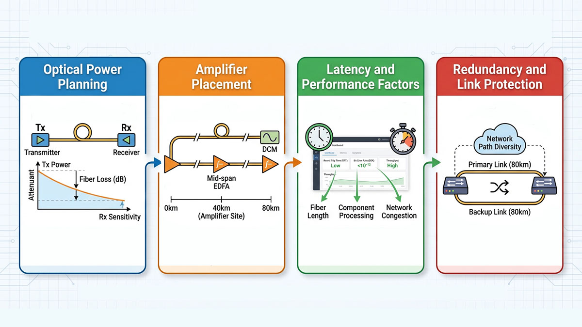
Optical Power Planning
Optical power planning determines whether an 80km link can operate within the module’s link budget while maintaining sufficient margin for aging, temperature changes, and connector loss.
| Parameter | Typical Range | Deployment Impact |
|---|---|---|
| TX output power | High | Supports long reach |
| Receiver sensitivity | Very sensitive | Enables weak signal detection |
| Optical budget | ~23–30dB | Defines max link loss |
Engineers should calculate total expected loss:
-
Fiber attenuation (~0.22–0.25dB/km)
-
Splice loss
-
Connector loss
-
Patch panels
-
Safety margin (≥3dB recommended)
Decision checklist:
-
Measure actual fiber length
-
Estimate total attenuation
-
Compare with module optical budget
-
Confirm sufficient margin
-
Verify DOM monitoring support
If the calculated link loss approaches the module’s maximum budget, additional measures such as amplification or cleaner fiber paths may be required.
Amplifier Placement
Most QSFP 40G 80km links are designed for direct-detect operation without amplification, but mid-span optical amplifiers may be required when link loss exceeds safe margins.
| Scenario | Amplifier Need | Typical Placement |
|---|---|---|
| ≤60km low-loss fiber | Not required | Direct link |
| 70–80km clean path | Possibly not required | Direct link |
| High-loss path | Recommended | Mid-span EDFA |
| Multiple patch panels | Considered | Fiber midpoint |
Amplifiers may be considered when:
-
Fiber attenuation is higher than expected
-
Connector count is high
-
Link margin is below safe threshold
-
Environmental variation is significant
Common approaches:
-
EDFA mid-span placement
-
Optical attenuation balancing
-
DOM monitoring after activation
Amplifier use increases complexity and cost, so it is typically avoided unless necessary.
Latency and Performance Factors
QSFP 40G 80km links maintain low and predictable latency compared with multi-stage transport systems, making them suitable for DCI and enterprise backbone use.
| Factor | Impact on Performance |
|---|---|
| Propagation delay | ~5µs per km |
| FEC usage | Adds small latency |
| Amplification | Minimal impact |
| Switch processing | Platform dependent |
Performance considerations:
-
Fiber length determines base latency
-
FEC improves stability but adds microseconds
-
Amplifiers add negligible delay
-
Direct links avoid DWDM switching latency
These characteristics make 80km direct optical links suitable for:
-
Data replication
-
Financial networks
-
Enterprise backbone
-
Real-time applications
Redundancy and Link Protection
Long-distance 40G links should include redundancy and protection mechanisms to maintain availability during fiber or equipment failures.
| Protection Method | Purpose |
|---|---|
| Dual fiber paths | Physical redundancy |
| Ring topology | Fast reroute |
| Link aggregation | Load balancing |
| Automatic failover | Service continuity |
Recommended design practices:
-
Deploy diverse fiber routes
-
Use redundant modules and ports
-
Implement LAG or routing failover
-
Monitor optical power continuously
-
Test failover scenarios
Because 80km links often connect critical infrastructure—such as data centers or aggregation nodes—redundancy planning is essential for service continuity.
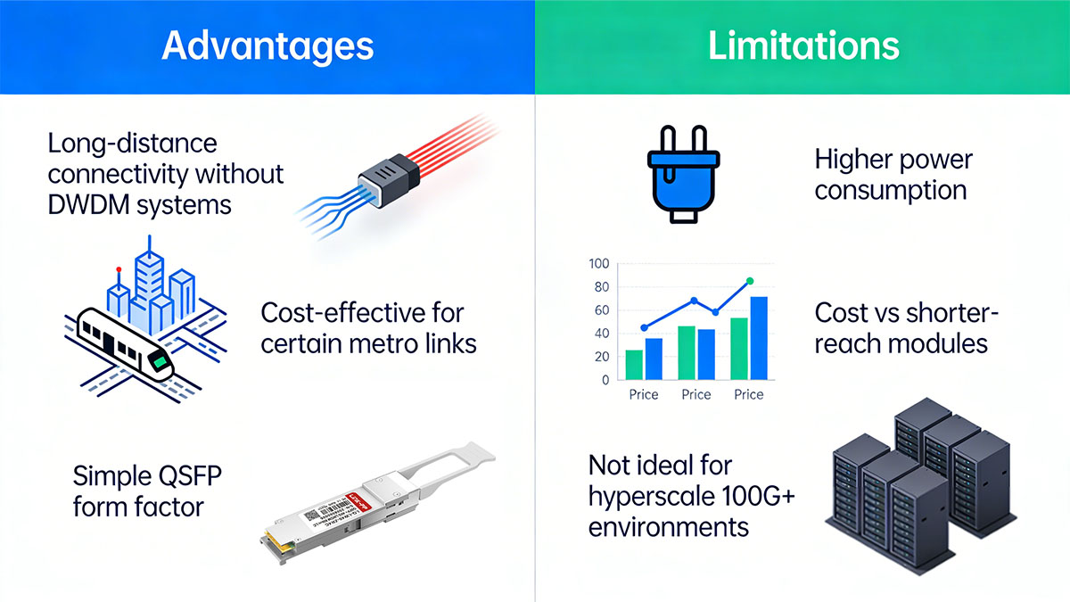
? Advantages and Limitations
QSFP 40G 80km modules provide a practical way to extend 40Gbps links across metro-scale distances without deploying full DWDM transport systems, but they come with higher power draw and are best suited to specific network scenarios. Understanding both the strengths and constraints helps determine when these modules are the right engineering and cost decision.
Advantages
1. Long-Distance Connectivity Without DWDM Systems
QSFP 40G 80km modules enable direct 40Gbps transmission across up to 80km of single-mode fiber without requiring a full DWDM transport platform.
| Approach | Complexity | Typical Use |
|---|---|---|
| Direct 40G 80km optics | Low | Metro/DCI links |
| DWDM transport system | High | Multi-channel long haul |
| Coherent optics | Medium–high | High-capacity backbone |
Because these modules operate in a standard QSFP+ form factor with duplex LC fiber, they allow point-to-point long-distance links using existing switching hardware and dark fiber infrastructure. This simplifies deployment for networks that need extended reach but do not require multi-channel optical transport.
2. Cost-Effective for Certain Metro Links
For links between roughly 40km and 80km, QSFP 40G 80km optics can be more cost-effective than deploying coherent transport or upgrading entire links to 100G.
Key cost advantages:
-
Reuse existing 40G switches
-
Avoid DWDM chassis and amplifiers
-
Lower operational complexity
-
Faster deployment timeline
This is especially relevant in:
-
Metro DCI
-
Regional backbone links
-
Enterprise inter-city connectivity
-
Telecom aggregation
However, cost efficiency depends on maintaining existing 40G infrastructure. If a network is already migrating to 100G, coherent solutions may provide better long-term value.
3. Simple QSFP Form Factor
Despite their long reach, these modules retain the standard QSFP+ form factor, allowing installation in many 40G switch and router platforms.
| Feature | Benefit |
|---|---|
| QSFP+ form factor | Easy installation |
| LC duplex interface | Standard SMF cabling |
| DOM support | Real-time monitoring |
| Direct detect optics | Simpler architecture |
This simplicity allows:
-
Quick deployment
-
Minimal additional hardware
-
Straightforward maintenance
-
Familiar operational procedures
For networks already running QSFP-based 40G ports, the upgrade to 80km reach often requires only module replacement and link validation.
Limitations
1. Higher Power Consumption
QSFP 40G 80km modules consume more power than LR4 or ER4 optics due to higher transmit power and receiver sensitivity requirements.
| Module Type | Typical Power |
|---|---|
| SR4/LR4 | Low |
| ER4 | Moderate |
| 80km optics | High |
Implications:
-
Increased thermal load on switches
-
Reduced port density in some systems
-
Need to verify port power limits
-
Potential airflow planning requirements
Some legacy switches may not support high-power QSFP modules even if the optical interface is compatible.
2. Cost vs Shorter-Reach Modules
Compared with LR4 or ER4 optics, 80km modules are more expensive and should only be used when the distance requirement justifies the additional cost and complexity.
Decision considerations:
-
Use LR4 if ≤10km
-
Use ER4 if ≤40km
-
Use 80km optics only when necessary
-
Avoid over-specifying reach
Deploying 80km modules on shorter links can introduce unnecessary cost and may require optical attenuation to prevent receiver overload.
3. Not Ideal for Hyperscale 100G+ Environments
QSFP 40G 80km optics are less suitable for hyperscale or rapidly scaling environments where 100G or higher bandwidth is becoming the standard.
| Network Type | Suitability |
|---|---|
| Legacy 40G metro | Suitable |
| Enterprise backbone | Suitable |
| Hyperscale DC | Limited |
| 100G migration networks | Transitional only |
Limitations in these environments:
-
Limited bandwidth scalability
-
Higher per-bit cost vs 100G
-
Potential obsolescence during upgrades
-
Inefficient for large-scale growth
As networks migrate to 100G and beyond, 40G 80km modules are increasingly used as transitional or niche solutions rather than long-term infrastructure for hyperscale deployments.
? How to Choose the Right QSFP 40G 80km Module
Choosing the right QSFP 40G 80km module requires matching optical budget, platform compatibility, and network roadmap rather than selecting based on reach alone. Because 80km links operate close to power and loss limits, incorrect selection can result in unstable links or unnecessary cost.
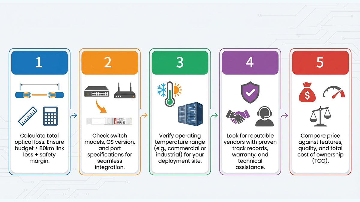
The following decision framework helps ensure the module fits both the physical link and the network architecture.
Step 1: Confirm Distance and Link Loss
The first decision point is whether the actual fiber path and total attenuation fall within the module’s optical budget with sufficient margin.
| Link Condition | Recommended Module |
|---|---|
| ≤10km | LR4 |
| 10–40km | ER4 |
| 40–80km | 80km optics |
80km | Consider coherent |
Key checks:
-
Measure actual fiber length
-
Calculate attenuation (fiber + connectors)
-
Add safety margin (≥3dB)
-
Compare with module link budget
-
Confirm stable RX power range
If the calculated link loss approaches the maximum optical budget, consider a higher-margin module or improved fiber path.
Step 2: Verify Switch and Router Compatibility
Not all 40G platforms support high-power long-reach QSFP modules, so hardware compatibility must be verified before purchase.
| Compatibility Item | Why It Matters |
|---|---|
| Port power budget | High-power optics required |
| Thermal capacity | Prevent overheating |
| Firmware support | Module recognition |
| FEC capability | Improves stability |
Checklist:
-
Confirm switch supports extended-reach QSFP
-
Check vendor compatibility list
-
Update firmware if needed
-
Verify DOM monitoring support
-
Confirm FEC configuration
Selecting a module without confirming platform support is one of the most common causes of deployment failure.
Step 3: Choose Proper Vendor Coding
Vendor-compatible coding ensures the module is recognized and operates correctly in the target switch or router.
| Coding Option | Use Case |
|---|---|
| OEM-coded | Strict vendor environments |
| Multi-vendor coded | Mixed networks |
| Custom-coded | Specific platforms |
Considerations:
-
Match coding to switch vendor
-
Ensure DOM and alarms function
-
Verify EEPROM integrity
-
Confirm acceptance by platform
In many networks, vendor-coded modules simplify deployment and reduce compatibility troubleshooting.
Step 4: Evaluate Link Environment
The physical fiber environment determines whether a standard 80km module is sufficient or if additional margin is required.
| Environment Factor | Impact |
|---|---|
| Fiber quality | Determines attenuation |
| Patch panels | Add loss |
| Splices | Reduce margin |
| Temperature variation | Affects stability |
Decision logic:
-
Clean, low-loss fiber → standard 80km module
-
High-loss path → higher-margin model
-
Near 80km limit → test before deployment
-
Uncertain fiber → measure first
Understanding the actual link environment helps prevent underestimating loss.
Step 5: Consider Future Network Plans
Module selection should align with long-term network upgrades, especially if migration to 100G or higher is planned.
| Network Plan | Recommendation |
|---|---|
| Stable 40G network | Deploy 80km module |
| Gradual 100G migration | Transitional use |
| New build | Evaluate 100G instead |
| Rapid growth | Consider coherent |
Questions to ask:
-
Will this link remain 40G long term?
-
Is bandwidth growth expected soon?
-
Is a DWDM system planned?
-
Is this a temporary or permanent link?
Choosing a module aligned with the upgrade roadmap avoids premature replacement.
Final Selection Checklist
The right QSFP 40G 80km module balances optical reach, hardware compatibility, and long-term network strategy.
Before final selection:
-
Confirm distance and link loss
-
Verify switch compatibility
-
Match vendor coding
-
Evaluate fiber environment
-
Check power and thermal limits
-
Consider future upgrades
After installation:
-
Monitor DOM optical levels
-
Validate error-free operation
-
Track margin over time
A structured selection process ensures stable long-distance performance while avoiding unnecessary cost or compatibility issues.
? FAQs About QSFP 40G 80km
Can a QSFP 40G 80km module be used on shorter links?
Yes, but optical attenuation may be required to avoid receiver overload on very short fiber spans. These modules transmit at higher optical power, so links under ~10–20km should be evaluated carefully.
Does a QSFP 40G 80km link always require optical amplification?
No, most 80km links are designed to operate without amplification if total link loss stays within the module’s optical budget. Amplifiers are only needed when attenuation exceeds safe margins.
What fiber type is required for 40G 80km modules?
QSFP 40G 80km modules require single-mode fiber (typically OS2) with low attenuation and minimal connector loss. Multimode fiber is not supported.
Are QSFP 40G 80km modules compatible across vendors?
They can interoperate if optical specifications and wavelengths match, but using the same module type at both ends is recommended for maximum stability. Vendor coding must also be compatible with the host switch.
Do all switches support QSFP 40G 80km optics?
No, some switches cannot support the higher power and thermal requirements of long-reach modules. Always verify platform compatibility, firmware support, and port power limits before deployment.
How much latency does an 80km 40G link add?
Fiber propagation delay is roughly 5µs per kilometer, so an 80km link adds about 400µs one-way latency, excluding switching and FEC overhead. Direct optical links typically have predictable latency.
When should I choose 40G 80km instead of 100G coherent?
Choose 40G 80km when existing infrastructure is 40G and bandwidth needs are stable; choose coherent 100G when scaling capacity or exceeding 80km distance. The decision depends on upgrade timeline and cost efficiency.
What is the typical power consumption of QSFP 40G 80km modules?
They typically consume more power than LR4 or ER4 optics due to higher transmit output and receiver sensitivity. Check switch port power limits before installation.
? Conclusion
QSFP 40G 80km transceivers provide a practical and proven solution for extending 40Gbps connectivity across metro-scale distances without moving to complex DWDM or coherent systems. They are especially valuable for data center interconnect, telecom aggregation, campus backbones, and disaster-recovery links where existing 40G infrastructure is still in active use and stable bandwidth is sufficient.
However, successful deployment depends on more than reach specifications alone. Engineers must validate optical budget, fiber quality, switch compatibility, and long-term network roadmap before selecting an 80km module. When properly planned, these transceivers deliver reliable long-distance performance with a familiar QSFP form factor and relatively straightforward deployment model.
For organizations operating established 40G environments, QSFP 40G 80km modules remain a cost-efficient way to extend network reach while maintaining operational simplicity. As networks evolve toward 100G and beyond, they can also serve as a transitional solution for regional links that do not yet require higher-speed coherent optics.
If you are evaluating deployment options or need help selecting compatible modules for your switches and link distance, explore professional-grade solutions and technical guidance from the LINK-PP Official Store. Their portfolio includes tested QSFP 40G long-reach optics designed for interoperability, stability, and real-world metro-distance applications.







