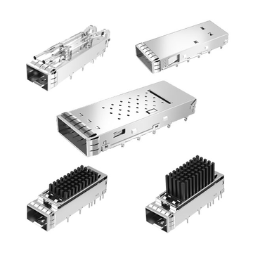
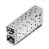
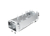
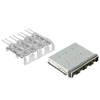

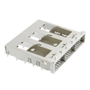

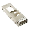
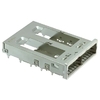
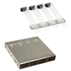
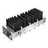


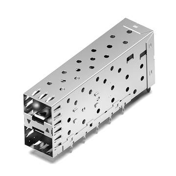



An OSFP Cage Assembly helps reduce electromagnetic interference (EMI) around high-speed optical interfaces through its metal enclosure, EMI Spring Fingers, and proper contact with the equipment bezel. These features work together to create a more continuous shielding and grounding path, helping limit unwanted electromagnetic emissions from affecting nearby electronic components.
EMI shielding is especially important in high-speed network equipment, where multiple optical ports and electronic circuits operate close together. Even small gaps or poor electrical contact between metal components can weaken the overall shielding structure. Understanding how these parts work together helps equipment designers select and install a suitable cage assembly.
Understanding EMI Shielding in an OSFP Cage Assembly
EMI shielding uses conductive materials and proper grounding connections to help control unwanted electromagnetic energy. In an OSFP interface, the metal cage surrounds the optical module and works with the equipment bezel to form a protective conductive structure. This helps contain electromagnetic emissions and reduce interference with nearby electronic circuits.
What Is EMI Shielding in an OSFP Cage Assembly?
EMI shielding is a method of limiting unwanted electromagnetic emissions and reducing their effects on nearby electronic components. It commonly uses conductive metal structures to provide a barrier around areas that may generate or receive electromagnetic interference.
In an optical transceiver interface, the metal cage provides the main enclosure around the module. When properly connected to the equipment chassis, it helps create a conductive shielding path that limits electromagnetic leakage through gaps around the interface.
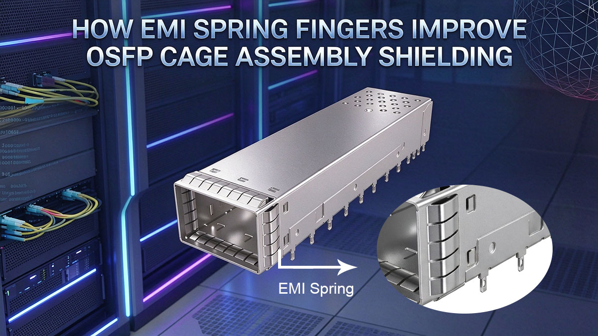
EMI Spring Fingers are flexible metal contact features positioned around the cage. They help maintain electrical contact between the cage and the surrounding bezel, reducing gaps in the shielding structure.
Why EMI Shielding Matters in High-Speed Equipment
High-speed network equipment contains electronic circuits that operate at high data rates. These circuits can generate unwanted electromagnetic energy, which may affect nearby components if the equipment does not have adequate shielding.
EMI control becomes more important when multiple optical ports, connectors, and circuit boards are installed in a limited space. Without proper shielding, electromagnetic emissions from one area may interfere with other nearby electronic circuits.
Effective shielding helps equipment designers manage several important requirements:
- Reduce Electromagnetic Emissions: Help limit unwanted electromagnetic energy escaping from the equipment enclosure.
- Protect Nearby Components: Reduce the risk of electromagnetic interference affecting surrounding electronic circuits.
- Support Equipment Compliance: Help the complete system meet applicable electromagnetic compatibility (EMC) requirements.
The cage, bezel, and grounding connections must work together to provide the intended shielding performance.
Common EMI Issues Around OSFP Interfaces
EMI problems around optical interfaces often result from gaps or incomplete electrical contact between metal components. Even when a metal cage is properly installed on the PCB, poor contact with the equipment bezel can weaken the overall shielding path.
Several common issues deserve attention:
- Insufficient Grounding Contact: Poor electrical contact between the cage and bezel can interrupt the intended grounding path.
- Gaps Around the Interface: Incorrect bezel openings or poor mechanical alignment may leave gaps that allow electromagnetic energy to escape.
- Improper Spring Finger Compression: If the contact fingers do not press properly against the bezel, they may fail to establish reliable electrical contact.
- Damaged Contact Features: Bent or deformed spring fingers may reduce contact quality and affect shielding continuity.
These issues show why shielding depends on more than the metal enclosure itself. Proper contact, mechanical alignment, and grounding connections are also important.
How EMI Spring Fingers Improve OSFP Cage Assembly Shielding
EMI Spring Fingers help improve shielding by maintaining electrical contact between the metal cage and the equipment bezel. These flexible metal contacts help reduce gaps between conductive parts, creating a more continuous grounding path around the optical interface.
Their effectiveness depends on proper contact position, suitable compression, and the overall cage and bezel design. When these conditions are met, they help maintain the intended shielding structure.
How EMI Spring Fingers Work
EMI Spring Fingers are small, flexible metal features designed to maintain contact between two conductive surfaces. They are typically positioned around the cage where it meets the equipment bezel.
When the cage is installed, the bezel presses against these contact fingers. Their spring-like shape allows them to flex slightly while maintaining pressure against the mating surface.
This contact helps reduce open gaps between the metal cage and bezel. It also provides an electrical connection that allows the surrounding metal structures to work together as part of the EMI shielding enclosure.
The main functions of these contact features include:
- Flexible Contact: Adjust to small differences in the mating surfaces during installation.
- Electrical Connection: Connect the cage to the surrounding metal bezel.
- Gap Reduction: Help limit openings between conductive parts of the enclosure.
How Spring Fingers Help Establish Grounding
Grounding is an important part of EMI shielding because it provides an electrical connection between conductive components. In an optical interface, the cage needs a suitable connection to the equipment chassis to help maintain the intended shielding path.
EMI Spring Fingers help establish this connection by pressing against the conductive surface of the bezel. When the contact is properly designed and installed, electrical continuity can be maintained between the cage and chassis.
Several factors influence the quality of this connection:
- Contact Position: Spring Fingers must meet the intended conductive area of the bezel.
- Contact Pressure: Sufficient compression helps maintain stable electrical contact.
- Surface Condition: Clean and suitable contact surfaces help reduce resistance at the connection point.
A reliable grounding path helps the cage and chassis function as a connected shielding structure rather than separate metal parts.
Maintaining EMI Shielding Continuity
Shielding continuity refers to maintaining an effective conductive connection across the metal enclosure. If gaps or poor electrical contacts exist between connected parts, the shielding structure may become less effective.
EMI Spring Fingers help address this issue by maintaining contact between the cage and bezel, including around areas where the two components meet. Their flexible design helps accommodate small mechanical variations without losing the intended contact.
To maintain effective shielding continuity, designers should consider:
- Consistent Contact: Ensure the contact fingers meet the bezel at the intended positions.
- Suitable Compression: Avoid insufficient contact pressure or excessive deformation.
- Secure Installation: Keep the cage properly positioned to maintain contact during equipment assembly.
These details help the metal cage, spring contacts, and equipment bezel work together as a more continuous EMI shielding structure.
OSFP Cage Assembly and Bezel Contact Requirements
Proper contact between the cage and equipment bezel is important for maintaining an effective EMI shielding structure. The bezel must align with the cage correctly so that the EMI Spring Fingers can make reliable contact with its conductive surface.
The opening size, contact position, and installation alignment all affect how these components fit together. Incorrect dimensions or poor positioning may prevent the spring contacts from working as intended.
Proper Spring Finger Contact with the Bezel
EMI Spring Fingers need to touch the intended conductive area of the bezel to establish an electrical connection. This contact helps connect the metal cage to the equipment chassis and maintain the shielding path around the optical interface.
The bezel should provide enough contact area for the spring fingers to remain engaged after installation. If the fingers miss the intended surface or touch an unsuitable area, the electrical connection may become unreliable.
When checking this contact, consider the following points:
- Contact Position: Ensure the spring fingers meet the designated bezel contact area.
- Contact Surface: Use a suitable conductive surface at the contact points.
- Contact Consistency: Check that the fingers maintain contact across the required positions.
Bezel Cutout and Compression Requirements
The bezel cutout must match the mechanical dimensions and position of the cage assembly. Its opening should allow the optical module to fit correctly while providing the necessary contact area for the EMI Spring Fingers.
Compression is also important. When the equipment bezel is assembled with the cage, it should press the spring fingers enough to maintain electrical contact without excessively deforming them.
Several design details require attention:
- Cutout Dimensions: Follow the cage manufacturer's mechanical drawings and applicable OSFP specifications.
- Compression Range: Maintain the specified spring finger compression to support reliable contact.
- Clearance: Allow enough space for proper module insertion and removal without interfering with surrounding structures.
Incorrect cutout dimensions or excessive compression may cause poor contact, mechanical interference, or damage to the spring contacts.
Why Proper Cage and Bezel Alignment Matters
Correct alignment ensures that the cage and bezel meet at their intended contact positions. Even small positioning differences may cause some spring fingers to miss the contact area or experience uneven compression.
PCB mounting position, bezel location, and cage mechanical tolerances should therefore be considered together during equipment design.
To maintain proper alignment:
- Match Mechanical Dimensions: Check the cage dimensions against the equipment bezel drawings.
- Verify Mounting Position: Confirm that the cage is correctly positioned on the PCB.
- Check Contact Engagement: Ensure the spring fingers meet the bezel evenly after assembly.
Proper alignment helps maintain consistent electrical contact and reduces the risk of installation-related EMI shielding problems.
EMI Shielding in High-Density OSFP Cage Assembly Designs
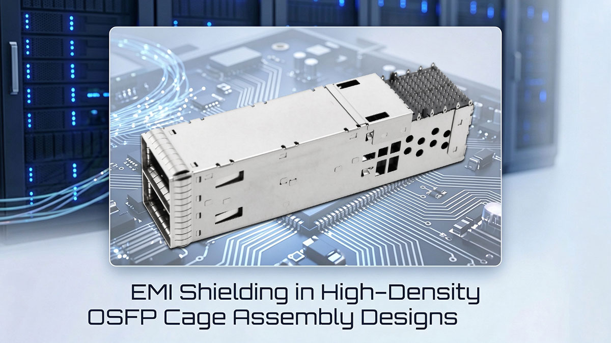
High-density cage designs require careful EMI shielding across multiple optical ports. When several cages are installed close together, their contact positions, spring finger placement, and bezel fit must work together to maintain the intended shielding structure.
Single-port and multi-port configurations may have different mechanical layouts, but both require reliable electrical contact between the cage and equipment enclosure. Proper spring finger placement helps maintain this contact across the required areas.
EMI Shielding in Multi-Port OSFP Cage Designs
Multi-port cage designs place several optical modules within a shared equipment panel area. This arrangement saves space and increases port density, but it also requires careful attention to the shielding around each interface.
Each port needs suitable contact between its metal cage and the surrounding bezel. If the contact is incomplete at one interface, it may create a gap in the intended shielding structure.
When designing multi-port configurations, consider the following factors:
- Individual Port Contact: Ensure each cage has the required contact with the equipment bezel.
- Cage Spacing: Follow the specified mechanical spacing to prevent interference between adjacent structures.
- Shared Grounding Structure: Check that the cages and chassis maintain the intended grounding connections.
These considerations help maintain consistent shielding across equipment with multiple optical interfaces.
Spring Finger Placement in Stacked Cage Assemblies
Stacked cage assemblies arrange multiple optical ports in vertical rows to increase front-panel density. Their compact structure requires careful placement of EMI Spring Fingers to ensure proper contact with the corresponding bezel areas.
The position of each contact feature should match the cage layout and equipment panel design. If the upper or lower contact fingers are misaligned, they may not achieve the required compression after installation.
The following table highlights key considerations for different cage configurations:
| Cage Configuration | EMI Shielding Considerations | Design Focus |
| 1x1 Single-Port Cage | Maintain proper contact around the individual port | Bezel contact and alignment |
| 1xN Multi-Port Cage | Check contact positions across multiple horizontal ports | Port spacing and contact consistency |
| 2x1 Stacked Cage | Confirm contact at both upper and lower port areas | Vertical alignment and finger placement |
| 2xN Stacked Cage | Maintain suitable contact across multiple rows and columns | Bezel fit and overall shielding continuity |
The exact spring finger arrangement depends on the specific cage design. Equipment designers should follow the manufacturer's mechanical drawings rather than assume that all configurations use the same contact layout.
Bezel Contact Across Multiple OSFP Ports
In high-density equipment, several optical cages may share a common front-panel bezel. Each cage must meet the designated contact areas to help maintain electrical continuity between the individual metal structures and the equipment chassis.
A suitable bezel design should provide the correct openings, contact surfaces, and mechanical clearances for all installed ports. The position of each opening must match the corresponding cage so that the EMI Spring Fingers can engage properly.
When checking bezel contact across multiple ports, pay attention to:
- Opening Alignment: Match each bezel cutout with its corresponding cage position.
- Contact Coverage: Confirm that the required spring finger contact areas are properly engaged.
- Mechanical Clearance: Avoid interference between adjacent cages, contact features, and panel structures.
- Consistent Installation: Check that all ports maintain their intended contact after the complete assembly is installed.
A properly matched bezel and cage layout helps maintain the shielding structure across multiple optical ports. This is especially important in stacked and high-density equipment where several interfaces occupy a limited space.
Common OSFP Cage Assembly Installation Issues Affecting EMI Shielding
Installation quality can affect how well a cage maintains EMI shielding. Even when the product has properly designed EMI Spring Fingers, incorrect positioning, insufficient contact, or physical damage may weaken the intended electrical connection with the equipment bezel.
Checking these details during assembly helps identify potential contact problems before the equipment enters operation. Three common issues deserve particular attention.
Insufficient Spring Finger Contact
Insufficient contact occurs when the EMI Spring Fingers do not press properly against the conductive bezel surface. This may happen when the bezel opening is incorrectly positioned, the cage is misaligned, or the contact features do not receive the specified compression.
Poor contact can increase electrical resistance at the connection point and weaken the intended grounding path. It may also create gaps in the overall shielding structure.
To check for insufficient contact:
- Inspect Contact Position: Confirm that the spring fingers meet the designated bezel contact areas.
- Check Compression: Compare the installed condition with the manufacturer's specified compression range.
- Verify Electrical Continuity: Use an appropriate test method to check the connection between the cage and chassis.
Proper contact helps maintain a reliable electrical connection across the metal enclosure.
Incorrect Bezel and PCB Alignment
The cage is mounted on the PCB, while the bezel is normally fixed to the equipment chassis. Their relative positions must match the mechanical design to ensure that the spring fingers contact the correct bezel areas.
If the PCB mounting position or bezel location is incorrect, the cage may sit too high, too low, or at an angle. This can cause uneven spring finger compression or prevent some contact points from engaging.
Common alignment issues include:
| Alignment Issue | Possible Cause | Potential Effect |
| Cage Position Offset | Incorrect PCB mounting position | Spring fingers miss the intended contact area |
| Bezel Misalignment | Incorrect panel installation | Uneven contact across the cage |
| Incorrect Cutout Dimensions | Bezel opening does not match the cage drawing | Poor fit or mechanical interference |
| Uneven Cage Position | PCB or mounting tolerance variation | Inconsistent spring finger compression |
Before final assembly, compare the PCB layout, cage mechanical drawing, and bezel dimensions. This helps identify positioning differences that could affect contact quality.
Spring Finger Damage During Installation
EMI Spring Fingers are flexible metal features, but they can become bent or deformed if handled incorrectly. Excessive force, improper insertion, or contact with surrounding metal edges may damage these features during equipment assembly.
Damaged fingers may lose their intended spring force or fail to reach the correct contact area. As a result, the electrical connection with the bezel may become inconsistent.
To reduce the risk of damage:
- Follow the Installation Direction: Insert the cage according to the manufacturer's assembly instructions.
- Avoid Excessive Force: Do not force the cage into an opening that does not match its mechanical dimensions.
- Inspect Contact Features: Check for bent, flattened, or deformed fingers after installation.
- Replace Damaged Parts: Follow the manufacturer's guidance if contact features cannot maintain their specified shape.
Careful handling helps preserve the contact structure and supports consistent EMI shielding throughout equipment assembly.
How to Choose an OSFP Cage Assembly for Better EMI Shielding
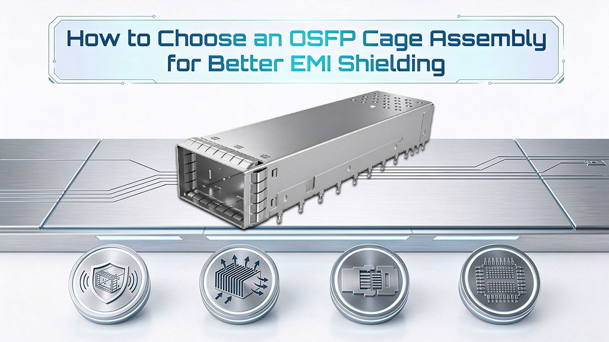
Choosing the right cage requires more than checking its port configuration and mounting style. Buyers should also consider the EMI Spring Finger structure, bezel compatibility, PCB mounting requirements, and available product specifications to ensure the assembly fits the intended equipment design.
A suitable product should match both the mechanical layout and the required shielding configuration. Checking these details before ordering can help reduce installation problems and avoid unnecessary design changes.
Check EMI Spring Finger Configuration
EMI Spring Fingers are an important feature to check when selecting a cage. Their position and contact arrangement should match the equipment bezel design to establish the intended electrical connection.
Different products may use different EMI contact configurations. Before making a selection, consider the following details:
- Spring Finger Position: Check whether the contact features match the required areas around the cage and bezel.
- EMI Containment Features: Confirm whether the product uses internal, external, or other specified EMI contact structures.
- Contact Design: Review the product drawings to understand the spring finger arrangement and surrounding metal structure.
For example, LINK-PP LP11SC01000M is an OSFP 1x1 cage featuring EMI Spring Fingers and an EMI-shielded design. It uses a through-hole, right-angle mounting structure with press-fit termination, making it an option for equipment layouts that require a single-port OSFP cage with EMI contact features.
Its product specifications and mechanical drawing can help engineers review the mounting structure and contact configuration before selecting it for a PCB design.
Confirm Bezel and PCB Compatibility
The selected cage must fit both the PCB layout and the equipment bezel. Even when a product has the required EMI Spring Fingers, differences in mounting positions or panel dimensions may prevent proper installation.
Before ordering, compare the following specifications:
| Compatibility Check | What to Confirm | Why It Matters |
| Cage Dimensions | Width, height, and length | Ensure the cage fits the available equipment space |
| PCB Footprint | Hole positions and mounting layout | Match the cage with the host board |
| Mounting Type | Press-fit or solder termination | Ensure compatibility with the PCB assembly process |
| Bezel Cutout | Opening dimensions and contact positions | Allow proper spring finger engagement |
| Port Configuration | 1x1, 1xN, or stacked layout | Match the required number and arrangement of ports |
| Module Compatibility | OSFP form factor and mechanical interface | Ensure the intended module fits the cage |
For press-fit designs, also check the PCB hole specifications and the manufacturer's recommended installation tooling. Incorrect hole dimensions or excessive insertion force may damage the mounting features.
Check EMI Specifications and Test Results
Product specifications and test information help buyers understand whether a cage meets their equipment requirements. Instead of relying only on the product description, review the available technical documents and confirm the relevant details with the manufacturer.
The following information is useful when evaluating a potential product:
- EMI Features: Confirm the listed spring finger configuration and shielding-related design features.
- Mechanical Drawings: Review dimensions, mounting positions, and contact locations.
- Electrical Continuity: Check whether the cage-to-chassis grounding connection meets the design requirements.
- EMI Test Results: Request relevant shielding or EMC test data when available and confirm the test conditions.
- Installation Requirements: Review press-fit specifications and recommended assembly procedures.
For example, LINK-PP LP11SC01000M lists EMI Springs as its EMI containment feature and provides product information for reviewing its mechanical configuration. Buyers can use these details to discuss specific compatibility or testing requirements with LINK-PP before placing an order.
Checking these documents before procurement helps ensure that the selected cage matches the equipment design rather than relying on general product descriptions alone.
Improve EMI Shielding with the Right OSFP Cage Assembly

Effective EMI shielding depends on more than the metal cage itself. EMI Spring Fingers, reliable grounding contact, proper bezel alignment, and correct installation all contribute to the shielding structure around an OSFP interface.
When selecting a cage, equipment designers should consider the following factors:
- EMI Spring Finger Design: Choose a contact configuration that matches the equipment's shielding requirements.
- Grounding Contact: Ensure the cage can establish reliable electrical contact with the bezel and chassis.
- Bezel Compatibility: Match the cage dimensions and contact positions with the equipment panel.
- Installation Quality: Follow the recommended mounting process to avoid damaged contact features or poor alignment.
LINK-PP offers OSFP Cage Assembly options for different equipment layouts and mounting requirements. You can review the available product configurations, mechanical drawings, and EMI-related features to identify a suitable solution for your projects.
For specific port configurations or customized contact requirements, contact our sales team to discuss product compatibility, technical specifications, and quotation options.
Visit the LINK-PP Official Store to explore OSFP Cage Assembly products or contact us for product specifications, compatibility support, and a quotation.